1. Introduction
Welcome to the YGN Effects Framework documentation! YGN IO Boards use a small AVR microcontroller to handle relay switching, LED states and power-on behaviour. Its firmware tells it how to respond to the footswitch and select the initial bypass state when you power up the pedal. In this guide, we’ll load that firmware and check that the board responds as expected.
We’ll use the Small IO Board, built around an ATtiny202, as our worked example. It receives its firmware through UPDI, the microcontroller’s programming interface. The Adafruit UPDI Friend connects your computer to that interface through a three-wire harness and a pogo-pin probe, whose spring-loaded contacts press against the board’s programming pads.
You won’t need to write code or install an IDE. We’ll prepare and check the harness, then use avrdude to write the pre-built firmware and the microcontroller’s configuration settings. After the write passes verification, we’ll disconnect the programming equipment and test the board’s switching behaviour.
Other IO Board variants may use different firmware, pin assignments or configuration settings. Follow along with the Small IO Board here, but use the matching firmware and programming instructions if you’re working with another variant.
2. Required Tools and Materials
Gather the items below before you start. We’ll first prepare the connection between the UPDI Friend and the pogo probe, then use it to load the firmware onto your IO Board.
There are two harness options: one uses the lead included with the UPDI Friend, while the other adds a JST PH connector. You only need one; we’ll walk through both in Preparing the UPDI Connection.
| Item | Purpose | Notes |
|---|---|---|
| Assembled IO Board | The board we’ll program | This guide uses the Small IO Board. Keep its 2×3 programming footprint accessible to the probe. |
| Adafruit UPDI Friend | Connects your computer to the microcontroller’s programming interface | We’ll set its voltage selector to 5 V before use. |
| 2×3 pogo-pin probe, 1.27 mm pitch | Makes temporary contact with the board’s programming pads | Use a probe with a 2×3 connector on its harness side. |
| UPDI harness | Connects the UPDI Friend to the pogo probe | Choose the included-lead adapter or the JST PH harness described later. |
| Wire, connector terminals and housings | Make the chosen harness | The connection section identifies the connectors for each option. Have wire cutters, wire strippers and a suitable crimping tool available if making the leads yourself. |
| Soldering iron and solder | Fit the optional JST PH connector to the UPDI Friend | Only needed if you choose that harness option. |
| Multimeter | Checks the harness before power is applied | Use continuity mode to check the intended connections and look for shorts. |
| Red paint marker | Marks pin 1 on the probe and harness connectors | Matching marks make orientation easier to check each time you connect them. |
| Computer and USB cable | Connects to the UPDI Friend and runs avrdude |
Use a USB cable that carries data. Software installation is covered next. |
| IO Board power supply | Powers the board for testing after flashing | Use the board’s normal supply connection for the functional checks. |
| Assembled effect board with footswitch and status LED | Tests switching and LED behaviour | Needed for the complete functional test. You can perform the basic relay check with the IO Board alone. |
Keep USB and board power disconnected for now. We’ll install the software, then assemble and check the programming connection before applying power.


3. Software Setup
We’ll use avrdude to communicate with the UPDI Friend and write the firmware to the ATtiny202. You don’t need an IDE or a compiler because we’ll use a pre-built firmware file.
Install avrdude for your platform, then check that your terminal can run it. No hardware connection is needed for this check.
| Platform | Installation |
|---|---|
| Linux | sudo apt install avrdude on Debian/Ubuntu, sudo dnf install avrdude on Fedora or sudo pacman -S avrdude on Arch. |
| macOS | With Homebrew installed, run brew install avrdude. |
| Windows | Download a Windows build from the official AVRDUDE releases, extract it and add the folder containing avrdude.exe to your PATH. |
PATH is the list of folders your terminal searches for commands. Adding the AVRDUDE folder lets you run avrdude from the folder containing your firmware later.
Verify the installation
- Open a new terminal so it picks up any changes to
PATH. - Run
avrdudewithout arguments.
You should see the command-line options. This confirms that your terminal can find and launch the tool; communication with the board will be checked during flashing.
If the command isn’t found, check the installation and PATH, then open a new terminal and try again.
With the software available, we’re ready to prepare the harness and probe that connect the UPDI Friend to your board.
4. Preparing the UPDI Connection
We’ll now make the temporary connection that lets the UPDI Friend program your IO Board. The pogo probe presses against the board’s programming pads, so there’s no need to solder a programming header onto the board.
The Small IO Board has a 2×3 programming footprint under the ATtiny202. Its silkscreen labels this area ICSP, but the programming interface used here is UPDI.
Keep the UPDI Friend disconnected from USB and the IO Board disconnected from its power supply throughout this section.
Identify the connections
Although the footprint has six positions, we only need three connections:
- UPDI carries programming communication to the microcontroller.
- PWR connects to the board’s +5 V programming supply.
- GND provides the shared ground connection.
The other positions are NC, meaning “not connected”. Leave them empty when making the harness.
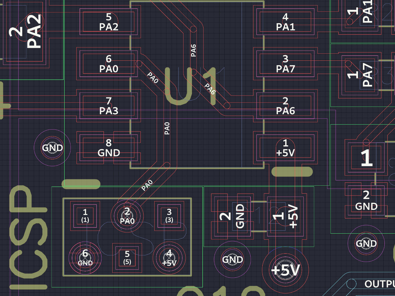
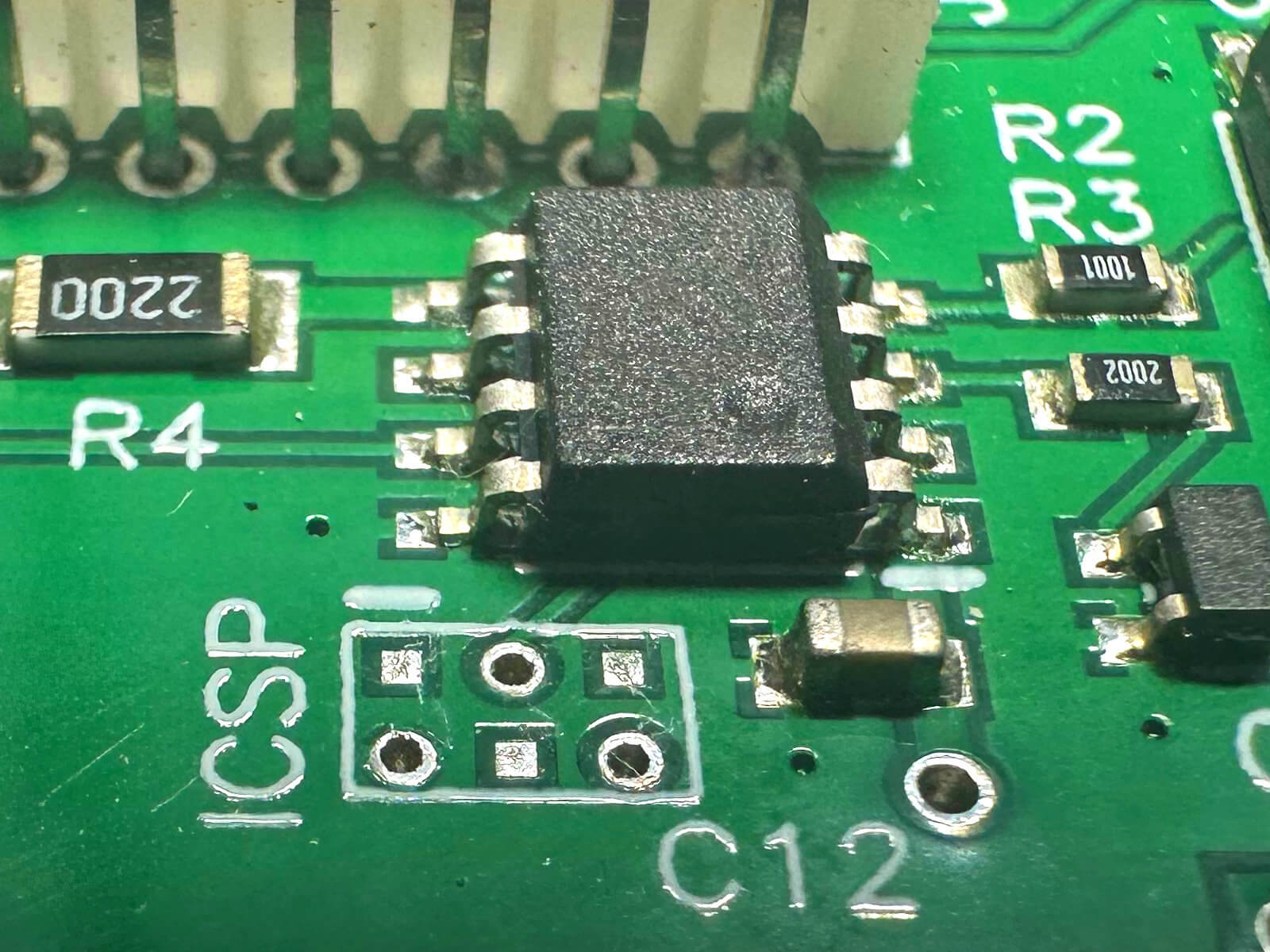
| Footprint pin | Function | Harness connection |
|---|---|---|
| 1 | NC | Leave unconnected |
| 2 | PA0 / UPDI | UPDI |
| 3 | NC | Leave unconnected |
| 4 | +5 V | PWR |
| 5 | NC | Leave unconnected |
| 6 | GND | GND |
Use the footprint illustrations to identify the numbering before arranging any wires. Connector positions appear reversed when viewed from the opposite face, so check which side you’re looking at.
Mark the orientation
We’ll mark pin 1 so the harness, probe and board are easier to line up each time we use them.
- Find the pin 1 marking beside the IO Board’s programming footprint.
- Identify the corresponding pin 1 contact on the pogo probe and mark that side with a small red paint dot.
- Identify pin 1 on the probe’s harness connector. Use your multimeter to trace the connection if its numbering is unclear.
- Mark the pin 1 side of the mating 2×3 harness housing with the same red dot.
There are two orientations to check: the harness must match the probe’s connector numbering, and the probe must match the board’s footprint numbering. The paint marks make those checks quicker, but the pin mapping is what establishes the correct connection.
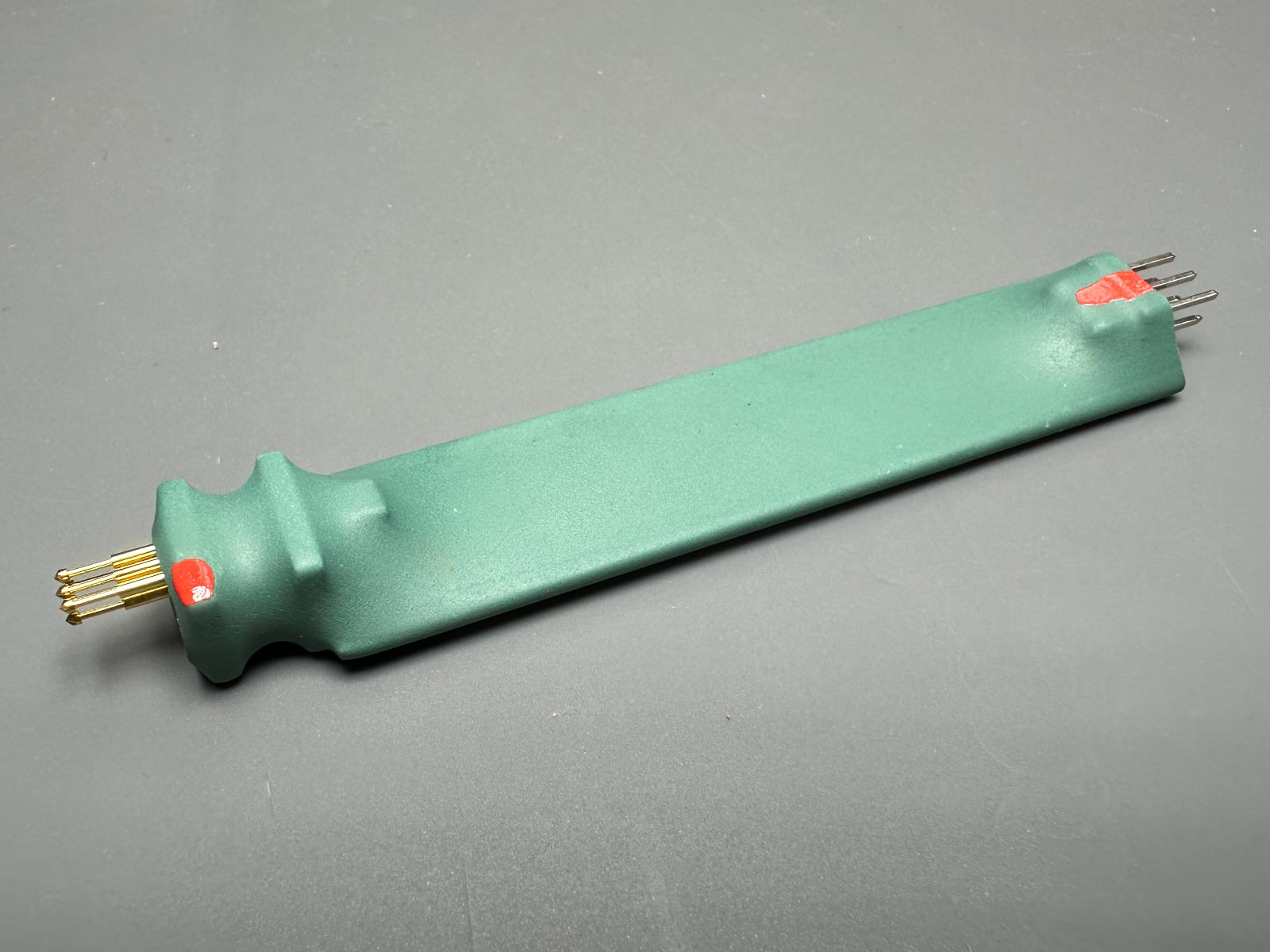
Note: With this footprint’s active connections confined to one row, turning the correctly wired probe 180° places them on unused pads. That reversed placement will not program the board. This does not protect against a miswired harness or a probe placed off the footprint, so still check alignment before applying power.
Make the harness
Both options below carry the same three signals. Choose the included-lead adapter if you want to use the UPDI Friend as supplied, or the JST PH option if you prefer that connector for your workshop harness.
Option A: Use the included JST SH lead
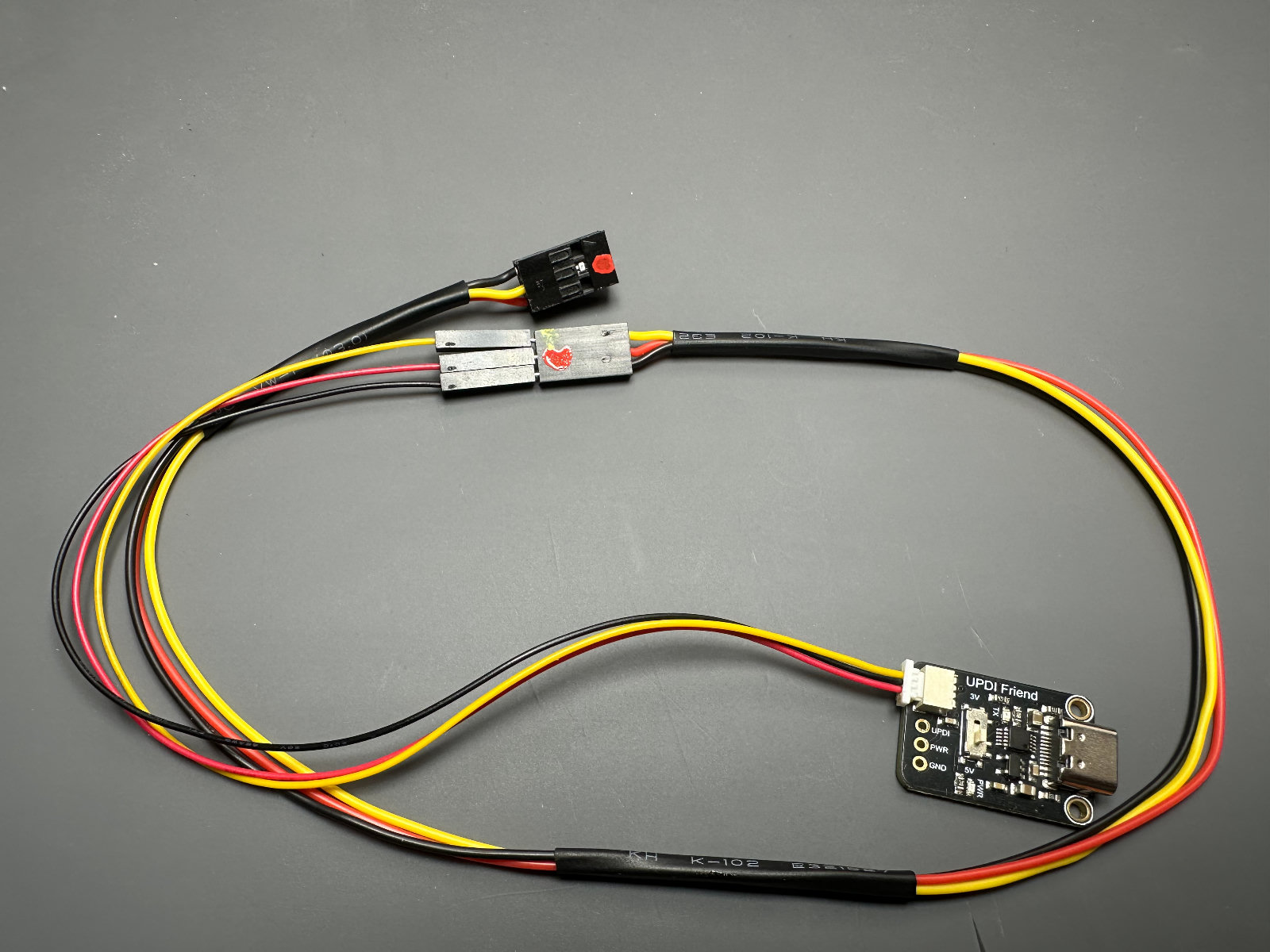
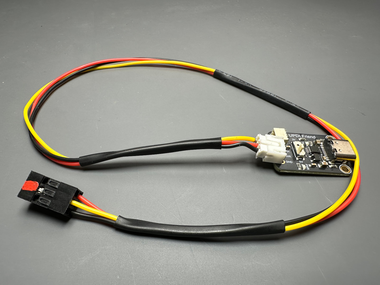
The UPDI Friend includes a JST SH lead ending in individual male Dupont pins. We’ll make a short adapter with a 1×3 female 2.54 mm housing at that end and a 2×3 female 2.54 mm housing at the pogo-probe end.
- Cut three wires to the same length and strip their ends for the terminals you’re using.
- Crimp a matching female terminal onto both ends of each wire.
- Insert three terminals into the 1×3 housing.
- Identify which position will receive each signal from the included lead: UPDI, PWR and GND. Follow the UPDI Friend’s labels rather than assuming a wire-colour order.
- Insert the other ends into the 2×3 housing: UPDI to pin 2, PWR to pin 4 and GND to pin 6.
- Leave positions 1, 3 and 5 empty.
- Gently tug each wire to check that its terminal is retained in the housing.
- Mark the matching sides of the included lead and 1×3 adapter so you can reconnect them in the same order.
Leave the adapter disconnected while we check its wiring below.
Option B: Add a JST PH connector
At YGN, JST PH is our go-to connector, so you may already have a few spares from another build. The UPDI Friend exposes UPDI, PWR and GND pads beside its JST SH connector. We can fit a three-pin JST PH header there and make a matching harness.
The exposed pads have 2.54 mm spacing, while JST PH uses 2.0 mm spacing. The header therefore needs a small adjustment to its leads before it will fit. Take your time with the fit before soldering.
- With USB disconnected, test-fit the three-pin JST PH header and gently adjust its leads to meet the exposed pads.
- Check that each lead enters its intended pad, then solder the header in place.
- Inspect the joints for solder bridges between adjacent pads.
- Cut three wires to the same length and strip their ends.
- Crimp the matching JST PH female terminals onto one end and terminals for the 2×3 female housing onto the other.
- Insert the PH terminals into their housing so they match the header’s UPDI, PWR and GND connections.
- Insert the other ends into the 2×3 housing: UPDI to pin 2, PWR to pin 4 and GND to pin 6. Leave positions 1, 3 and 5 empty.
- Gently tug each wire to check that its terminal is retained, then mark pin 1 at both ends.
Note: A JST XH connector is another option for the exposed pads. Remove the original JST SH connector first, since the SH and XH connectors will not fit side by side.
Check the harness
Before connecting the harness to the hardware, check that each wire reaches its intended position. A swapped terminal is much easier to correct now than to diagnose during flashing.
- Disconnect the harness from the UPDI Friend and pogo probe.
- Set your multimeter to continuity mode.
- Check each connection against the pinout table: UPDI to pin 2, PWR to pin 4 and GND to pin 6. Each intended pair should show continuity, usually with a beep or a reading close to zero ohms.
- Check for unintended continuity between the three separate wires, especially PWR and GND. They should not be connected to one another.
- If a connection is wrong, correct the terminal placement or crimp and repeat the checks.
- With USB still disconnected, connect the checked harness between the UPDI Friend and pogo probe. For Option A, include the supplied JST SH lead and check the order of its individual Dupont pins.
- Confirm the complete signal path from the UPDI Friend’s labelled connections to pogo contacts 2, 4 and 6.
Set the programming voltage
The Small IO Board connection in this guide uses 5 V.
- Set the UPDI Friend’s voltage selector to 5 V.
- Check that the selector is visibly in the 5 V position.
- Review the harness orientation and confirm that all three connections passed the continuity check.
Caution: Leave USB disconnected until the voltage selector, connector orientation and harness wiring have all been checked.
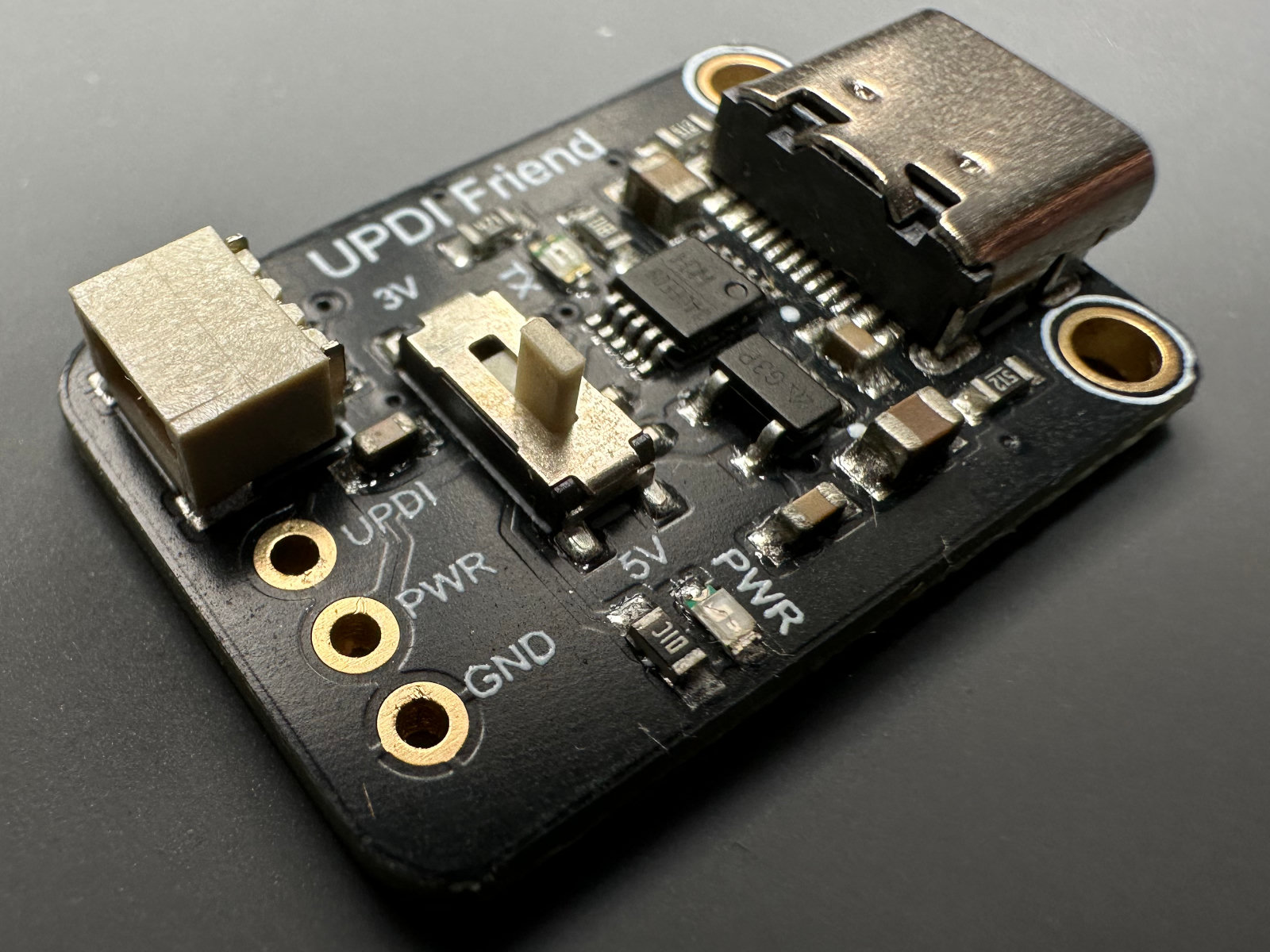

The harness and probe are now ready. Keep the IO Board’s normal power supply disconnected while we locate the firmware and prepare the flash command.
5. Flashing the Firmware
With the harness checked and the UPDI Friend set to 5 V, we’re ready to load the firmware. We’ll locate the file, identify the UPDI Friend’s serial port and run one command to write and verify the Small IO Board’s configuration and firmware.
Keep the IO Board’s normal power supply disconnected during programming.
Locate the firmware
The Small IO Board’s pre-built firmware is stored in the IO Board repository under:
small/firmware/small-standard-firmware/_output/firmware.hex
Open a terminal in that _output folder. If you downloaded firmware.hex separately, open the terminal in the folder where you saved it instead.
The command uses ./firmware.hex, which means “the file named firmware.hex in the current folder”. You don’t need to compile or edit this file.
Find your serial port
The UPDI Friend appears on your computer as a serial port. We need its name so avrdude knows which device to use.
- Leave the pogo probe off the IO Board for now.
- Check the available ports using the method below.
- Plug the UPDI Friend into your computer and check again. The new entry is its port.
| Platform | Typical port | How to find it |
|---|---|---|
| Linux | /dev/ttyUSB0 or /dev/ttyACM0 |
Run ls /dev/tty* before and after connecting the UPDI Friend. |
| macOS | /dev/tty.usbserial-XXXX |
Run ls /dev/tty.* before and after connecting the UPDI Friend. |
| Windows | COM3 or similar |
Check Device Manager > Ports (COM & LPT) before and after connecting the UPDI Friend. |
Note the port name, then unplug the UPDI Friend from USB while you position the probe.
Prepare the command and probe
The command writes both the firmware and the microcontroller’s fuse settings. Fuses are persistent configuration settings that control how the chip operates; they are separate from the firmware itself.
Caution: These settings are specific to the Small IO Board. For another IO Board variant, use its matching firmware and programming values.
Prepare this command as a single line, replacing /dev/ttyUSB0 with your port name. Don’t run it yet.
avrdude -c serialupdi -p t202 -P /dev/ttyUSB0 -b 57600 -U wdtcfg:w:0x00:m -U bodcfg:w:0x00:m -U osccfg:w:0x01:m -U tcd0cfg:w:0x00:m -U syscfg0:w:0xC4:m -U syscfg1:w:0x06:m -U append:w:0x00:m -U bootend:w:0x00:m -U flash:w:./firmware.hex:i
The pogo probe needs steady contact throughout writing and verification. Arrange the board and cable so you can hold the probe comfortably while starting the command.
- With USB disconnected, align the probe’s pin 1 mark with pin 1 on the board’s ICSP footprint.
- Press the probe onto the pads with gentle, even pressure. Each spring-loaded contact should sit over its corresponding pad.
- Plug the UPDI Friend into USB while keeping the probe steady.
- Run the prepared command.

Confirm the result
avrdude reports each configuration write, then writes the firmware and reads it back to verify the result. Keep the probe steady until the whole command finishes.
A successful run reports that the configuration values and flash were written and verified. The output will look similar to this:
Processing -U wdtcfg:w:0x00:m
Reading 1 byte for fuse0/wdtcfg from input file 0x00
Writing 1 byte (0x00) to fuse0/wdtcfg, 1 byte written, 1 verified

Processing -U bodcfg:w:0x00:m
Reading 1 byte for fuse1/bodcfg from input file 0x00
Writing 1 byte (0x00) to fuse1/bodcfg, 1 byte written, 1 verified

Processing -U osccfg:w:0x01:m
Reading 1 byte for fuse2/osccfg from input file 0x01
Writing 1 byte (0x01) to fuse2/osccfg, 1 byte written, 1 verified

Processing -U tcd0cfg:w:0x00:m
Reading 1 byte for fuse4/tcd0cfg from input file 0x00
Writing 1 byte (0x00) to fuse4/tcd0cfg, 1 byte written, 1 verified

Processing -U syscfg0:w:0xC4:m
Reading 1 byte for fuse5/syscfg0 from input file 0xC4
Writing 1 byte (0xC4) to fuse5/syscfg0, 1 byte written, 1 verified

Processing -U syscfg1:w:0x06:m
Reading 1 byte for fuse6/syscfg1 from input file 0x06
Writing 1 byte (0x06) to fuse6/syscfg1, 1 byte written, 1 verified

Processing -U append:w:0x00:m
Reading 1 byte for fuse7/append from input file 0x00
Writing 1 byte (0x00) to fuse7/append, 1 byte written, 1 verified

Processing -U bootend:w:0x00:m
Reading 1 byte for fuse8/bootend from input file 0x00
Writing 1 byte (0x00) to fuse8/bootend, 1 byte written, 1 verified

Processing -U flash:w:./firmware.hex:i
Reading 1435 bytes for flash from input file firmware.hex
Writing 1435 bytes to flash
Writing | ################################################## | 100% 1.42 s
Reading | ################################################## | 100% 0.50 s
1435 bytes of flash verified

Avrdude done.  Thank you.
The byte count and timings can differ between firmware builds. Look for confirmation that the flash was verified, with no errors. Verification confirms that the stored firmware matches the file; we’ll test the board’s switching behaviour next.
Once the command finishes successfully:
- Unplug the UPDI Friend from USB.
- Lift the pogo probe off the board.
The programming connection is now removed, and the board is ready for testing through its normal power input.
Troubleshooting
If flashing fails, keep the exact error message. It helps distinguish a computer-access problem from a missing file or an unreliable probe connection.
avrdude cannot open the serial port
For a Permission denied error on Linux, check your distribution’s instructions for serial-port access. Your account may need membership in a device-access group or a udev rule.
If the named port does not exist, check the UPDI Friend’s connection and identify its port again. The name may have changed after reconnecting.
avrdude cannot find firmware.hex
Check that your terminal is in the folder containing firmware.hex and that the filename matches the command exactly. The ./ path refers to your terminal’s current folder.
avrdude times out or reports initialization failed
Start with the temporary programming connection.
- Unplug the UPDI Friend from USB.
- Check that its voltage selector is still set to 5 V.
- Check the harness against the pinout table.
- Reseat the probe, checking pin 1 and making sure every contact sits over its pad.
- Reconnect USB and retry the command while holding the probe steady.
A loose probe contact can interrupt communication even when the harness is wired correctly. Check its seating before changing command settings.
Verification fails
Don’t treat an unverified write as a successful flash. Disconnect USB, check the harness and probe contact, then repeat the programming sequence.
If it fails again, keep the complete avrdude output so we can identify which write or verification operation stopped.
6. Testing the Board
The firmware has passed read-back verification. Now we’ll check how the board behaves when powered through its normal supply connection.
Start with the IO Board alone for a quick relay check. When you have an assembled effect board available, use the complete functional test to check the footswitch and status LED as well.
Basic IO Board check
The DIP switch selects the board’s power-on state. Setting it to ON gives us an audible cue when the firmware starts and activates the relay.
- Confirm that the UPDI Friend is disconnected from USB and the pogo probe has been removed from the IO Board.
- With board power disconnected, set the DIP switch to ON.
- Power the IO Board through its normal supply connection.
- Listen for a single relay click as the board initialises.
- Disconnect board power, set the DIP switch to OFF and power the board again. It should start in bypass without a relay click.
These two startup behaviours are expected. A silent startup with the DIP switch OFF is not, by itself, a sign that flashing failed.

Note: This basic check exercises startup and relay control. It does not verify the footswitch, status LED or wiring between the IO Board and effect board.
Disconnect board power before continuing to the complete test or installing the board.
Complete functional test
The effect board carries the footswitch and status LED that connect to the IO Board. Testing them together checks that a footswitch press reaches the firmware and produces the expected relay and LED response.
- With power disconnected and the pogo probe removed, connect an assembled effect board to the IO Board, including its footswitch and status LED.
- Set the IO Board’s DIP switch to ON.
- Power the pedal through its normal power input. The relay should click and the status LED should light.
- Press the footswitch. The relay should click and the LED should turn off.
- Press the footswitch again. The relay should click and the LED should light again.
- Disconnect power and set the DIP switch to OFF.
- Power the pedal again. It should start in bypass, with the LED off and no startup relay click.
- Press the footswitch to confirm that switching still works from this initial state.

If the relay or LED does not respond as expected, first check that flashing completed and passed verification. Then disconnect power before inspecting the effect-board connector, footswitch wiring, LED polarity and solder joints around the relay.
A successful test confirms the switching controls and LED behaviour. Listening to the pedal’s audio path is a separate check when testing the finished build.
Optional production test fixture
For repeated builds, you can make a removable test harness that plugs into the IO Board’s normal effect-board connector and provides a footswitch and LED. This lets you perform the same switching checks without connecting an effect board each time.
For a one-off build, using the assembled effect board is usually the simplest route. The fixture becomes useful when you have several IO Boards to test.
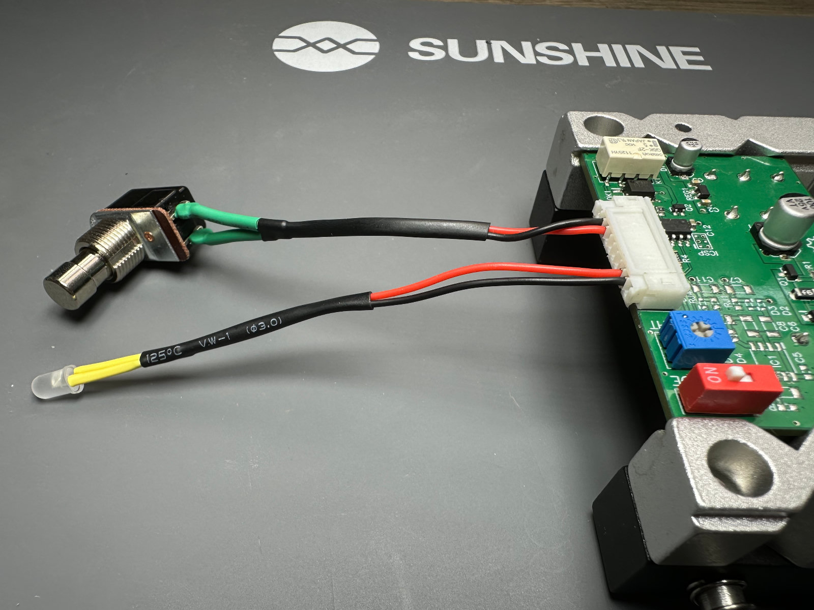
Wire the fixture according to the connector numbering shown in the illustration:
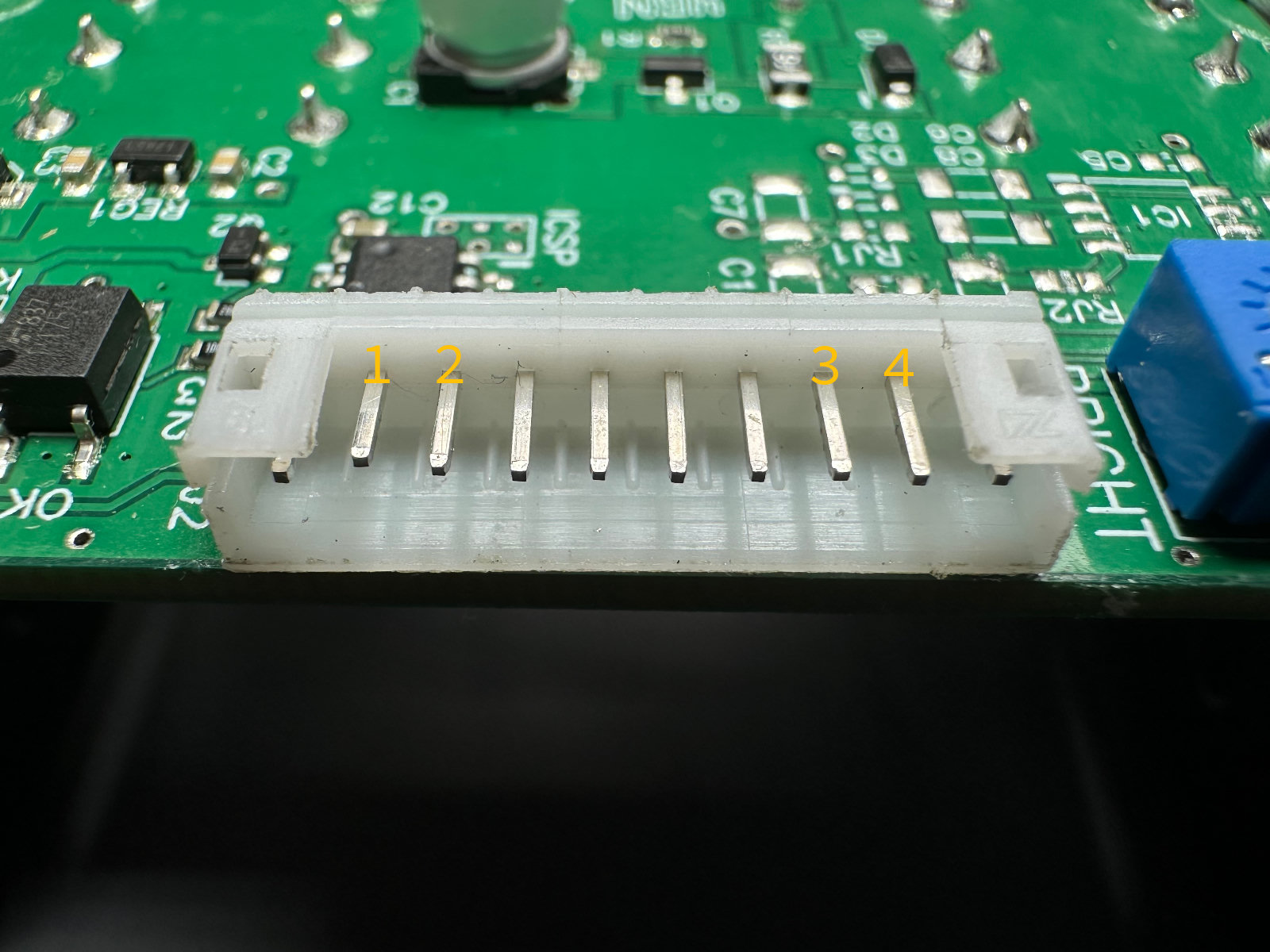
| Pin | Usage |
|---|---|
| 1 | Footswitch |
| 2 | Footswitch |
| 3 | LED anode |
| 4 | LED cathode |
The footswitch connects between pins 1 and 2. The LED’s polarity matters: connect its anode to pin 3 and cathode to pin 4.
Connect or remove the fixture only with board power disconnected. With it attached, follow the complete functional test above, using the fixture’s footswitch and LED.
Once testing is complete, disconnect power and remove the fixture if you used one. Your IO Board is now programmed and checked, ready for installation in the build.
Found an Issue?
Help improve this documentation by reporting errors or suggesting improvements.