An Open Hardware Framework for Effects
A standardized enclosure, IO Board and Effect Board that let you reuse everything around the circuit and concentrate on the part that changes.
Why We Standardize
Build the shared parts once. Spend your time on the circuit.
A pedal contains a lot of work that has nothing to do with the effect circuit.
There is the enclosure, control placement, power input, switching, external connections, wiring and assembly. None of those things disappear when the next circuit comes along, but building them from scratch every time means solving the same problems over and over again.
The YGN Framework gives those jobs a fixed home.
The enclosure defines the mechanical format. The IO Board handles the shared electrical infrastructure. The Effect Board contains the part that actually changes from one design to the next: the effect circuit itself.
Once those boundaries are defined, a new design can spend more of its complexity where it matters. You can prototype a new Effect Board, plug it into the same IO system and put it into an enclosure that already has known dimensions, mounting points and control positions.
We are perhaps slightly too fond of standardization, but that is the point. Solve the common parts once, document them properly and reuse them.
Everything needed to build, modify and manufacture the Framework is published under permissive licences: hardware, firmware, software, mechanical files and tooling.
The Architecture
Three parts, each with one job.
The Enclosure
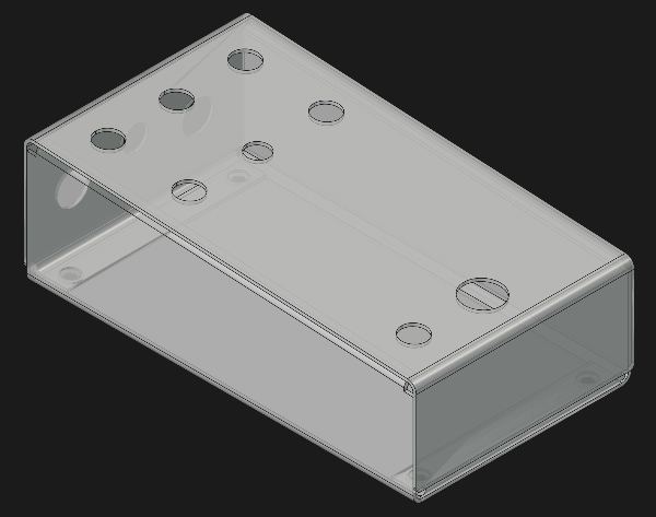
A standardized two-piece bent aluminium chassis that defines the mechanical format.
The IO Board
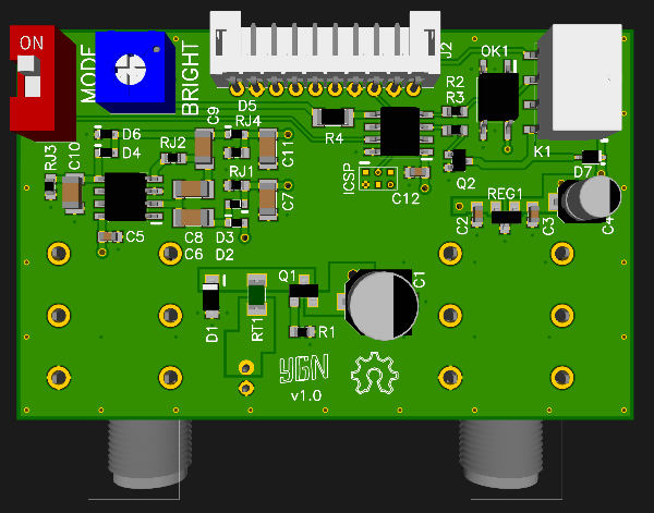
Handles power, switching and external connections shared between designs.
The Effect Board
Holds the audio circuit and front-panel controls specific to each effect.
Scalable Form Factors
Size S
126x41x70mm
The standard single-effect format, with one IO Board and one Effect Board.
Size M
126x41x140mm
Double width, with room for two Size S Effect Boards side by side and a Size M IO Board. Intended for dual effects and other designs that need the extra space.
Size L
A larger format intended for the digital effects platform. Currently in development.
The Enclosure System
We use a two-piece bent aluminium enclosure instead of a generic die-cast box. Its dimensions are designed around the Framework boards, control positions and connectors, giving every design the same mechanical starting point.
-
Bent aluminium construction: The enclosure is made from two formed sheet-aluminium parts. This gives us a repeatable internal geometry while keeping the construction relatively simple.
-
Easy access: Remove the cover and the boards, controls and connectors are immediately accessible. That makes assembly, troubleshooting and modification considerably less awkward.
-
Build it yourself: The enclosure can be made from the published dimensions using printable bending jigs. You can fabricate one in a small workshop without needing dedicated sheet-metal tooling.
-
Finish it however you like: Use a PCB or plastic faceplate, etch the aluminium, stamp it, apply decals or come up with something stranger. The enclosure defines the mechanical format, not what it has to look like.
The IO Board
Power, switching and external connections live on the IO Board so the Effect Board can concentrate on the effect itself.
-
Relay switching: An AVR microcontroller controls a DPDT relay, with optocoupler muting around the switching event. This keeps bypass control and switching logic off the Effect Board and gives every design the same switching interface.
-
Protected power input: Input filtering, reverse-polarity protection and over-voltage protection are handled on the IO Board before power reaches the effect circuit.
-
Optional voltage conversion: The IO Board can provide additional supply rails when a design needs them, with charge-pump options for -9V, 18V or ±15V operation. If an effect needs something other than the standard 9V supply, the rail is already available without adding the same conversion circuitry to every Effect Board.
-
Configuration: A DIP switch sets the default power-on state and an internal trimmer adjusts the brightness of the status LED.
-
One connection to the Effect Board: A 10-pin JST-PH cable carries the required connections between the IO Board and Effect Board. The interface stays consistent across the Framework, so the Effect Board does not need its own power jack, bypass relay or bundle of wires running to panel-mounted hardware.
The Effect Board
The Effect Board is where the actual effect circuit lives. The Framework defines its size, mounting points, connectors and control positions. Everything inside those boundaries is left to the design.
-
Fixed mechanical format: A Size S Effect Board uses a 73 × 62 mm PCB with known mounting points and clearances inside the enclosure. That gives a new circuit a mechanical target from the start, rather than defining the PCB and enclosure around each other every time.
-
Standard connections: JST-PH headers connect the Effect Board to the IO Board, footswitch and status LED. Power, audio connections and switching interfaces therefore stay consistent from one design to the next.
-
Defined control positions: Templates provide positions for up to six potentiometers or three potentiometers and three switches. The positions are standardized so the PCB, enclosure and faceplate can be designed around the same geometry.
-
No off-board signal wiring: Controls and connectors are mounted directly to the boards, with the shared connections routed through the standard headers. Once the PCB is assembled, the Effect Board plugs into the rest of the Framework without soldering wires between panel-mounted parts. The mechanical format is fixed. The circuit is yours.

Manufacturing and Tooling
The Framework includes the tooling used to make it.
Alongside the hardware and mechanical files, we publish bending jigs, assembly fixtures, stencil files and CAM where they make the process easier to reproduce.
The goal is repeatability with tools that are realistic for a small workshop. A basic 3D printer and desktop CNC can cover a surprising amount of the process when the tooling is designed around them.
We take a pragmatic approach to what should be made in-house. We do not make things ourselves simply for the sake of calling them DIY. We bring a process in-house when it gives us useful control, flexibility or repeatability.
-
Let board houses make the PCBs: Modern multilayer PCB fabrication is cheap, accurate and widely available. Milling or etching boards at home adds a lot of process for little benefit when professionally fabricated multilayer boards are cheap and readily available.
-
Bring assembly in-house where it makes sense: PCB assembly, on the other hand, is practical to handle on a small scale.. With a stencil, a repeatable paste process and a reflow setup, small batches can be assembled quickly without requiring industrial equipment. That is where the Framework tooling concentrates.
The Jigs
Stencil tooling
Models and CAM files make it possible to produce reusable solder-paste stencils from plastic sheet using a small CNC.
Paste application
Printable fixtures keep the PCB and stencil aligned during paste application, making the process faster and more repeatable.
Enclosure fabrication
Printable templates and bending jigs define the enclosure geometry so the same dimensions can be reproduced without dedicated sheet-metal tooling.
Docs & Licenses
The files are only useful if you can understand how to build and modify them, so the Framework is documented alongside the hardware, software and mechanical resources.
- Hardware (CC0): Public Domain. Use it, sell it.
- Software (CC0): Public Domain. Use it freely.
- Documentation (Apache 2.0): Free to share with attribution.
Roadmap
The digital platform is still in development. It is built around the FV-1 and extends the same Framework approach to DSP-based effects, with dedicated hardware and supporting development tools.
Follow the repo