1. Introduction
Welcome to the YGN Framework documentation! This guide will walk you through the process of fabricating a custom spoilboard designed to work perfectly with our 3D-printed CNC Holder. Building one of these is a simple but essential first step for accurately milling your pedal faceplates and PCB stencils.
Let’s get started!
What is a Spoilboard?
First things first, what exactly is a spoilboard? Think of it as a sacrificial, replaceable surface that sits between your CNC machine’s bed and the material you are cutting (your “stock”). Its job is to protect your machine’s bed from being accidentally cut and to provide a perfectly flat and stable surface to secure your workpiece.
Why a Perfectly Flat Spoilboard is Crucial
For jobs that require high precision on the Z-axis—like engraving a faceplate or milling a thin stencil—having a spoilboard that is perfectly parallel to your CNC’s gantry is non-negotiable. If the surface isn’t perfectly flat relative to the cutting tool’s path, your cuts will be deeper on one side than the other, resulting in an uneven finish or a ruined part. With CNC machining, preparation is everything. The process is extremely unforgiving: once you press “Start”, the machine will execute the code precisely as given, leaving no room for adjustments or errors.
To achieve this level of flatness, CNC operators perform a process called surfacing (or trimming). This involves using a large, flat-bottomed bit to have the CNC machine mill a very thin layer off the entire top of the spoilboard. This ensures the working surface is absolutely parallel to the machine’s own movements.
Tip: You can think of this process just like leveling the bed of a 3D printer. Just as bed leveling ensures a perfect first layer by creating a consistent distance between the nozzle and the build plate, surfacing a spoilboard ensures your cuts are perfectly consistent across the entire workpiece.
This guide will show you how to prepare a spoilboard for our CNC holder. While we will be making a spoilboard for a pedal faceplate, the process is identical for any other board you might need.
A Note on Software
In the project repository, you will find the FreeCAD files used to generate the toolpaths for surfacing the spoilboard. We also provide ready-to-use GRBL G-code files. However, these were generated for our specific setup: a stock 3018-PRO CNC with a 25mm surfacing bit.
Caution: Unless you have the exact same machine and bit, you should not use the provided G-code directly. You will need to open the FreeCAD file and adjust the CAM jobs and toolpaths to match your own machine’s parameters and bit choice. A detailed guide on how to do this is beyond the scope of this document.
2. Tools & Consumables
Spoilboard Material
Choosing the right material for a spoilboard is a balance. Ideally, you want the densest material possible that your machine can still surface cleanly. Materials like plywood are a poor choice because their layered construction can lead to tear-out and an uneven finish when surfaced. Plastics like acrylic can melt or gum up on the cutting bit, failing to produce a truly flat plane.
This leaves us with wood-based fiberboards, which are easy to work with and offer a good lifespan. The best choice among these is High-Density Fiberboard (HDF), sometimes sold as hardboard. The denser the board, the better it will hold up over time. Since we will be using tape to hold down our workpieces, the surface will degrade with each use. A denser board (ideally with a density of 1000 kg/m³ or higher) will resist tearing and last much longer.
Tools & Supplies
- Surfacing Bit: A large-diameter, flat-bottomed bit designed for planing and surfacing.
Note: The provided GRBL G-code is specifically for a 25mm surfacing bit. If you use a different size, you must adjust the toolpaths in the FreeCAD file accordingly.
- Shellac: While optional, applying a couple of thin coats of shellac after the spoilboard has been surfaced will help seal the fibers. This makes the board more durable and resistant to tearing when you remove the blue tape, significantly extending its lifespan.
3. Fabrication Process
-
Cut and Mark the Stock
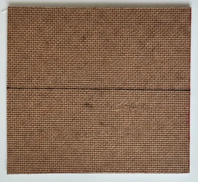
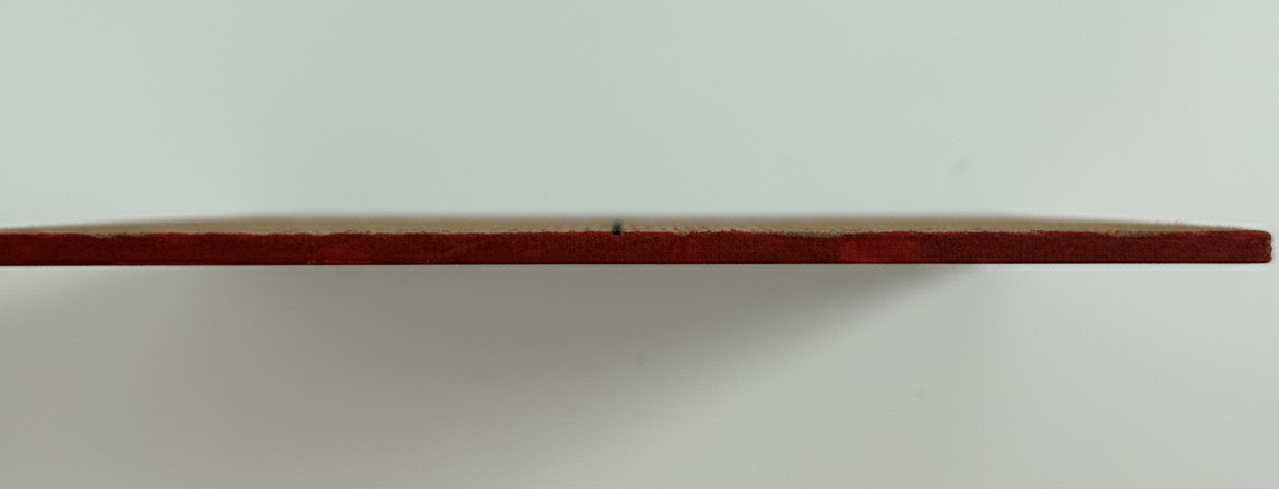
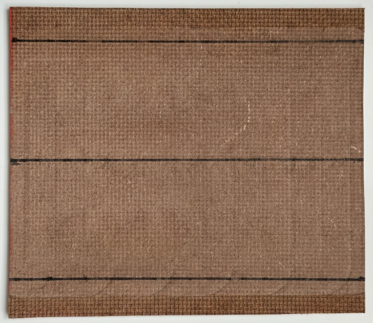
- Cut your HDF sheet to size. Our final spoilboard will be 110mm x 90mm. While you can cut the height to its final 110mm dimension, you must leave extra material on the width for clamping. The exact amount of extra width will depend on your specific clamping setup. For our example, we cut the stock to 110mm x 105mm.
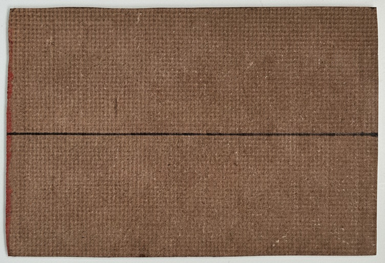
- Mark the center line across the width of the stock.
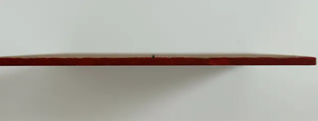
- Mark one of the short edges to designate it as the “bottom.” You can use a permanent marker or a bit of paint. This is a crucial step for consistency.
Tip: Once your spoilboard is surfaced, it is only flat in relation to the exact spot where it was milled. You must always place it in the same location and orientation on your CNC bed for it to work correctly. These markings ensure you do that every time.
-
Clamp the Stock to the Bed
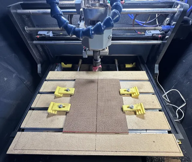
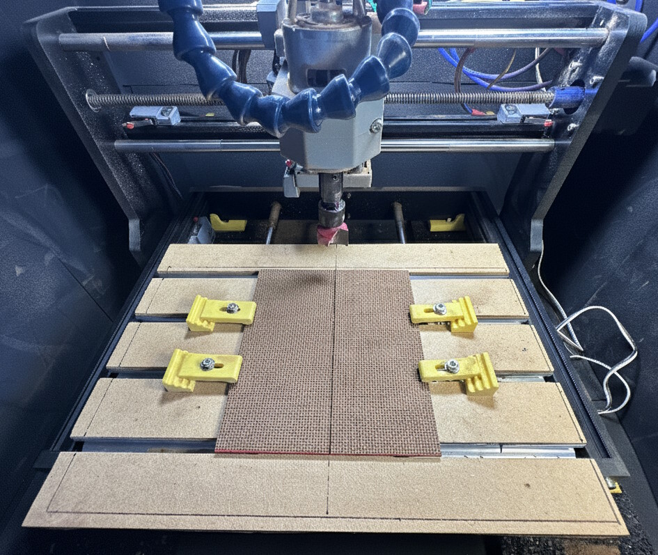
- Place the stock on your CNC machine’s bed. As mentioned before, a spoilboard must be surfaced in the exact location where it will be used. If you plan to use our custom 3D-printed holders, this location will always be the absolute center of your machine’s bed.
- Orient the stock so the painted “bottom” edge faces the front of your machine.
- Secure the stock firmly to the bed using your clamps on the extra material you left on the sides. Make sure it is held down tightly and cannot move at all.
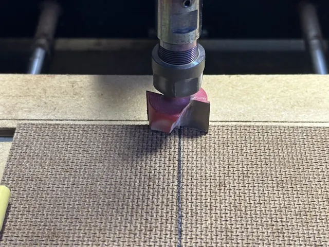
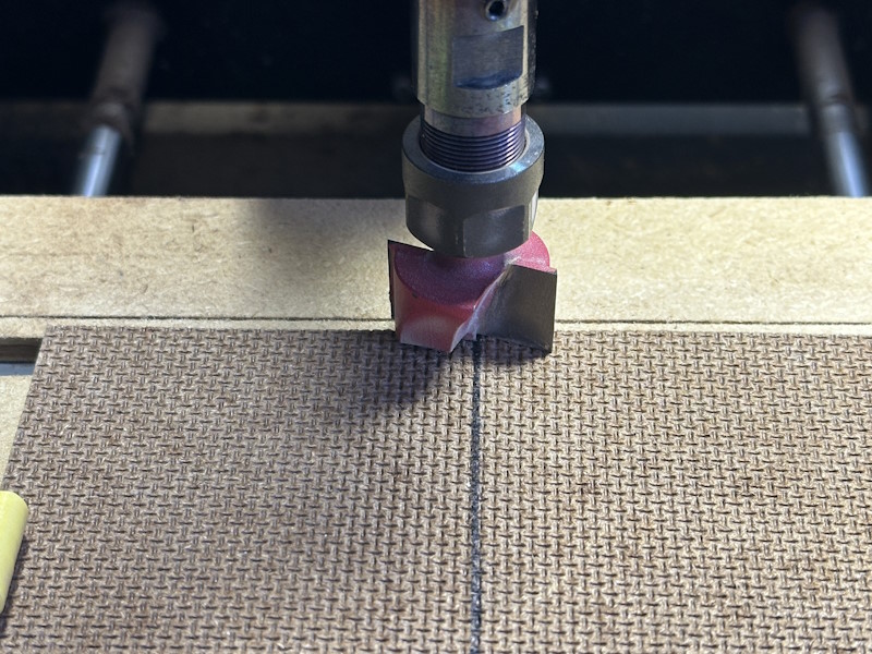
- Jog your machine’s spindle to the starting point for the surfacing job. If you are using the provided G-code, the job origin is the top center of the stock. Use your marked center line to position the bit perfectly.
-
Post-Processing and Final Cutout
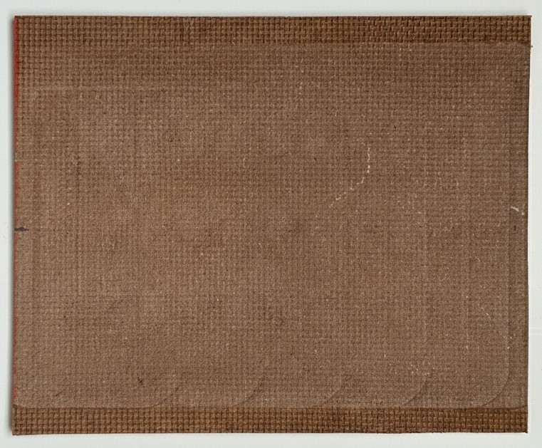
Once the surfacing job is complete, you can unclamp the board for the final steps.
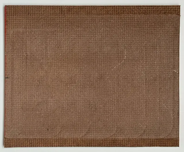
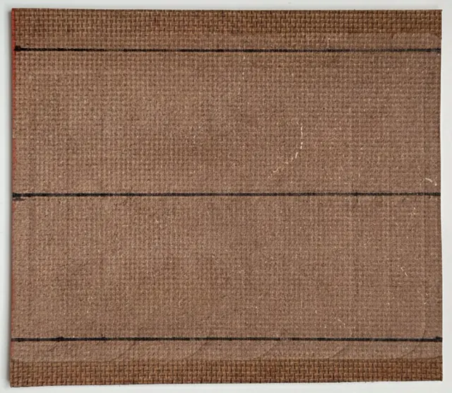
- Clean the board. Give the freshly surfaced side a very light scruff with fine-grit sandpaper (240 grit or higher). This is just to knock down any loose fibers that may have been pulled up during milling.Caution: Be very gentle. Just one or two light passes are all you need. The goal is to clean up the surface, not to remove material and undo the surfacing work you just did
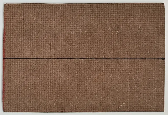
- Mark the final width. The surfaced area is now your reference. Since it was milled from the center, you can now re-draw your center line if it was removed during surfacing. From that center line, measure and mark the final edges of the spoilboard.
- Cut the excess material from the sides. You can use a utility knife with a fresh blade, a handsaw, or your tool of choice. Once the sides are trimmed, your spoilboard is officially ready to use!
-
Sealing with Shellac (Optional)
This final step is highly recommended as it will dramatically increase the lifespan of your spoilboard.Shellac is a natural resin that acts as a fantastic sealer. By applying a couple of thin coats, you will soak into and harden the top fibers of the HDF. This helps prevent the board from tearing when you remove the blue painter’s tape used to secure your faceplates and stencils.
- Ensure the spoilboard is completely clean and free of any dust from the previous steps.
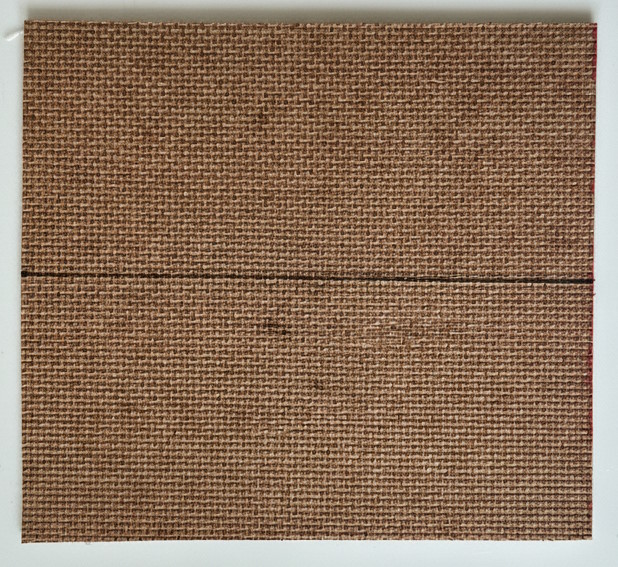
- Apply a thin layer of shellac using a clean rag or a folded paper towel. Work it into the surface in a circular motion. You only need a couple of thin coats.
- Let it dry completely. A properly applied shellac coat should not be glossy or thick. It will simply leave the surface looking slightly darkened and feeling sealed to the touch. Your spoilboard is now complete and ready for action!
Found an Issue?
Help improve this documentation by reporting errors or suggesting improvements.