1. Introduction
Welcome to the YGN Effects Framework documentation! This guide will help you set up the dedicated YGN FV-1 EEPROM Programmer. It connects your FV-1 target board to SpinASM for VS Code, letting you write compiled DSP programs to the EEPROM that stores your pedal’s programs without removing the chip from the board.
This is an alternative to the Arduino Pro Mini programmer. Both work with the same extension commands. On this board, the ATmega328PB microcontroller runs the programmer firmware and the FT230X USB-to-serial bridge carries communication between your computer and that microcontroller.
Before using the board for the first time, we’ll complete two setup steps:
- Flash the ATmega328PB. Load the pre-built firmware that tells the microcontroller how to program the target EEPROM.
- Configure the FT230X. Set its configurable pins for the board’s transmit and receive activity indicators and USB power detection.
These are one-time setup tasks. You won’t need to repeat them when changing your pedal’s DSP programs, and neither requires writing code or installing an IDE. The two tasks can be completed in either order; here, we’ll prepare the clip and flash the firmware first, then configure the USB bridge.
Once both are complete, we’ll connect the programmer to a target board and use SpinASM for an upload and read-back check. That final comparison confirms that the data written to the EEPROM matches the compiled program.
2. Required Hardware
Gather the items below before you start. We’ll use the AVRISP MK2 and SOIC clip to load the programmer firmware, then connect the programmer’s own USB interface to configure the FT230X.
The programmer needs an external 3.3 V supply throughout setup: neither its USB connection nor the AVRISP MK2 supplies that power. You can use the FV-1 target board’s supply or a bench supply for these initial steps. For the final test and normal EEPROM programming, the target board powers the programmer.
| Item | Purpose | Notes |
|---|---|---|
| YGN FV-1 EEPROM Programmer PCB | Connects SpinASM to the target EEPROM | If your board isn’t assembled yet, follow the assembly section below before making the programming connections. |
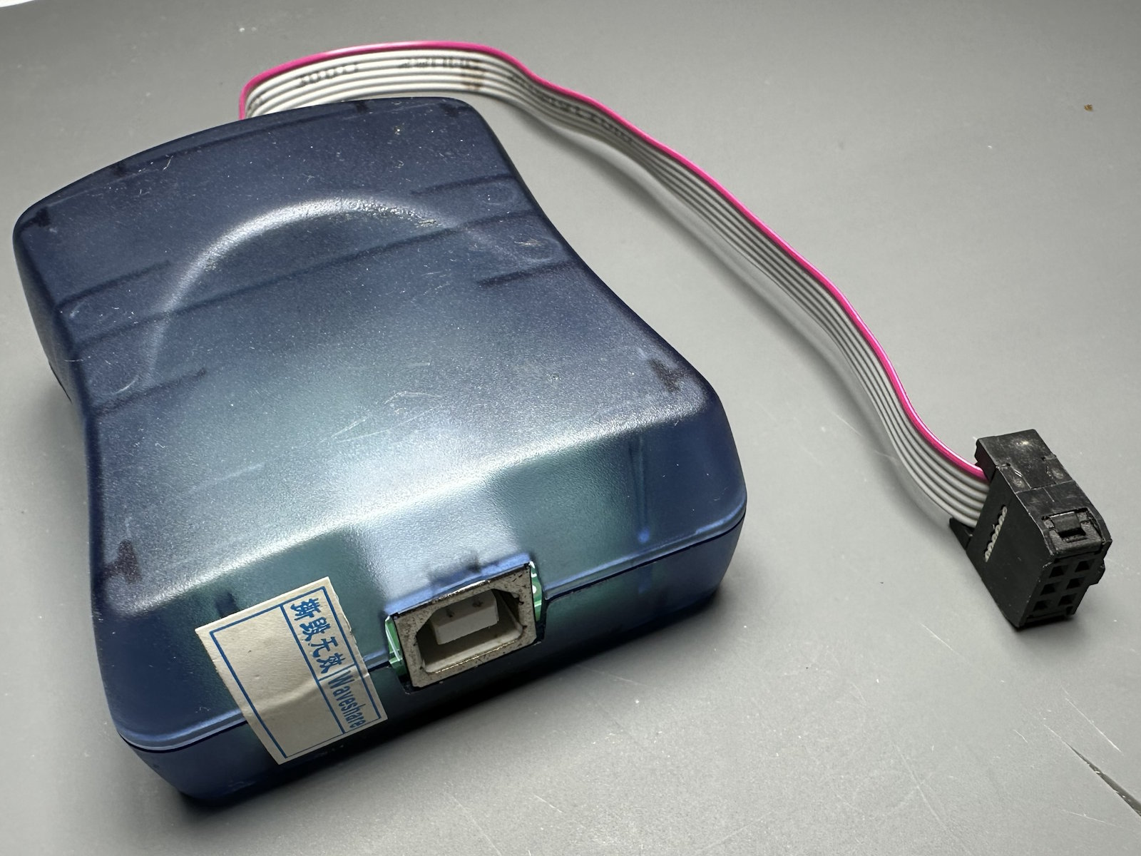
| AVRISP MK2 | Loads firmware into the ATmega328PB | This guide uses an AVRISP MK2. Other avrdude-compatible AVR ISP programmers may work, but their wiring and command options can differ. |
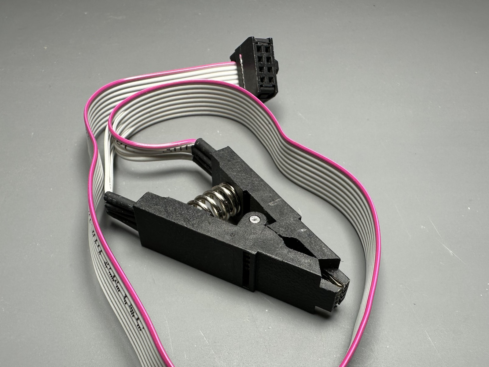
| SOIC8 test clip | Contacts the board’s SOICBite programming footprint | Use a clip with a 2×4 connector. We’ll adjust its contacts and identify its orientation before use. |
| Clip-to-ISP wiring | Adapts the clip’s 2×4 connector to the AVRISP MK2’s 2×3 connector | Choose individual male-to-male jumper wires or a crimped adapter harness. Both options are described in the clip section. |
| FV-1 target board and its power supply | Provides the EEPROM for the final test and powers the programmer during normal use | Use its dedicated programming header with SDA, SCL, FV-1 RESET, 3.3 V and GND. |
| 3.3 V bench power supply | Powers the programmer during setup if you aren’t using the target board | Optional. It connects to the programmer’s 3.3 V and GND pins. |
| Computer and USB cables | Runs the setup tools and connects to both programmers | We’ll cover avrdude for firmware flashing, then FT_PROG on Windows or ftdi_eeprom on Linux and macOS. Follow the SpinASM for VS Code guide for extension installation and project setup. |
| Multimeter | Checks the adapter harness before power is applied | Use continuity mode to check each connection against the wiring table. |
Keep everything disconnected for now. First, we’ll make sure the programmer board is assembled and ready, then prepare the clip and its wiring.
3. Programmer Assembly
If your programmer PCB is already assembled, you can continue to Prepare the SOIC Clip. Otherwise, start with the SMD PCB Assembly guide. Like every PCB in the YGN Effects Framework, this board uses the assembly techniques covered there.
We provide a dedicated stencil holder to keep the stencil aligned during solder paste application and a soldering jig to hold the through-hole components steady while you solder them. These tools help with the fiddly parts of assembly so you can concentrate on placing components and making good joints.
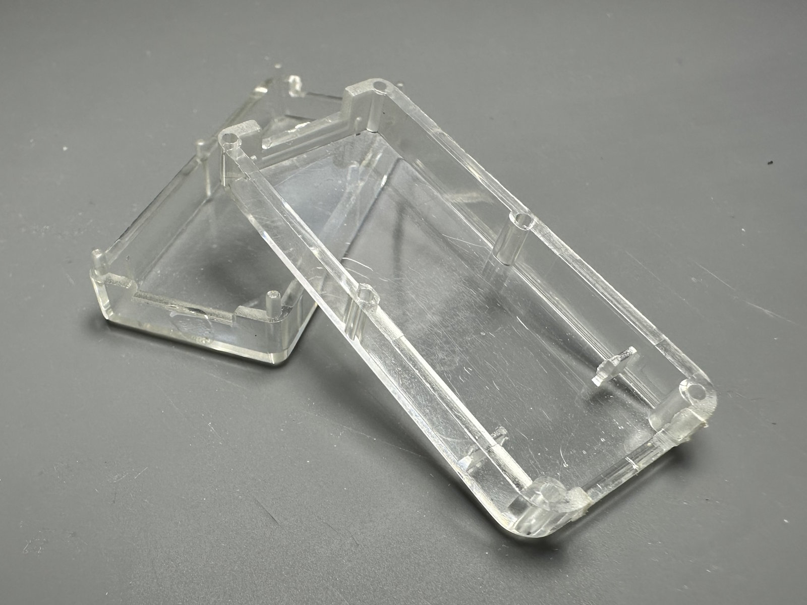
The programmer was designed before we had access to a 3D printer, so its home is an LK-USB07 ABS enclosure rather than one of our printed cases. You can usually find one by searching for LK-USB07 on Chinese online marketplaces such as AliExpress or Banggood.
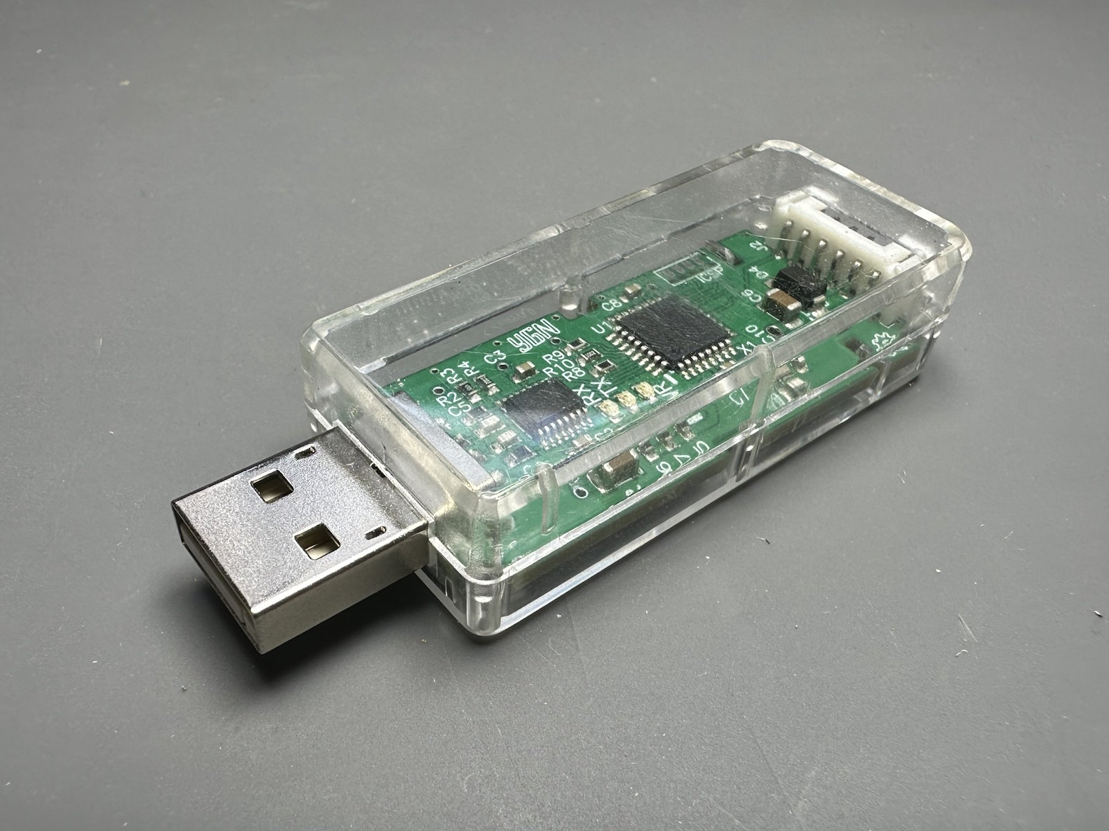
With the PCB assembled, leave power and USB disconnected. Next, we’ll prepare the clip that gives the AVRISP MK2 access to the programmer’s microcontroller.
4. Prepare the SOIC Clip
We’ll use the SOIC clip to make a temporary programming connection to the ATmega328PB. The programmer PCB has a SOICBite footprint, a set of pads designed for an inexpensive SOIC8 test clip. This gives us access to the microcontroller without adding a permanent programming header.
The footprint comes from the open-source SOICbite project. Although the clip normally grips an eight-pin chip, here it grips the PCB itself. We’ll adjust its contacts, check its orientation and make an adapter harness for the AVRISP MK2.
Keep the programmer unpowered and both USB connections disconnected throughout this section.
Adjust the clip
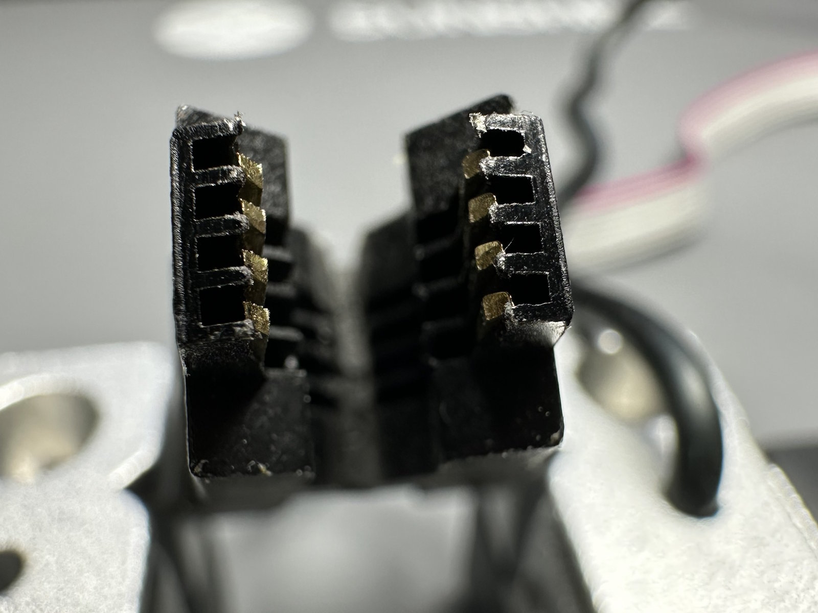
A stock SOIC8 clip may not close tightly enough to grip the SOICBite pads. A small adjustment brings its contacts inward so they can sit against the PCB.
- With the clip disconnected, bend the contacts on both jaws slightly inward. Work a little at a time and keep both rows even.
- Test-fit the clip on the footprint. Both jaws should close fully, with every contact sitting over its pad.
- If the clip feels loose or rocks on the board, remove it, adjust the contacts a little further and try again.
Caution: Bend the contacts gently. Bending them too far can weaken or misalign them.
Tip: Once adjusted, keep this clip for SOICBite connections. You should not need to reshape it again.
Identify pin 1 and orient the clip
The clip is not keyed, so it can be attached the wrong way round. Check its orientation each time you use it.
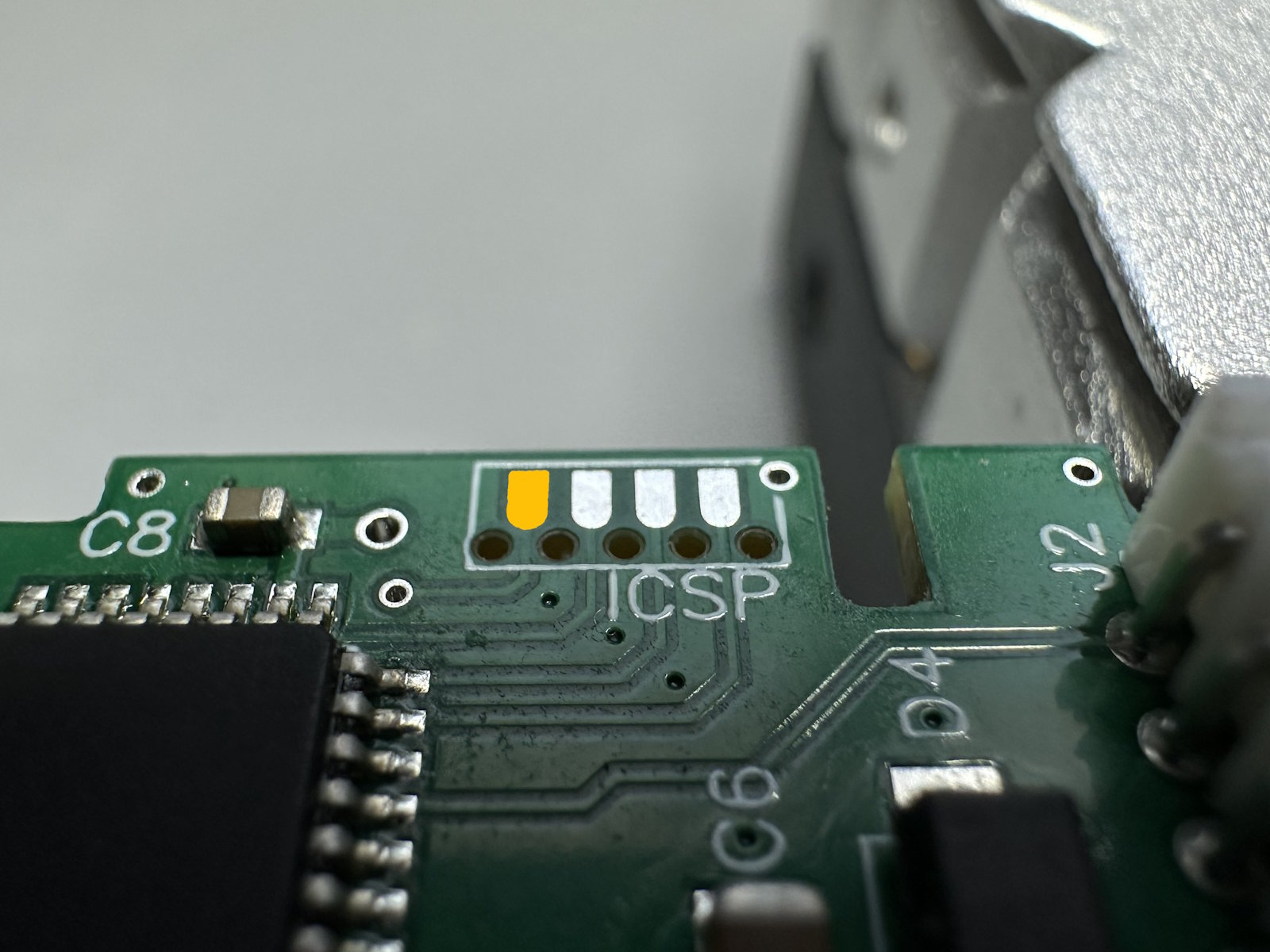
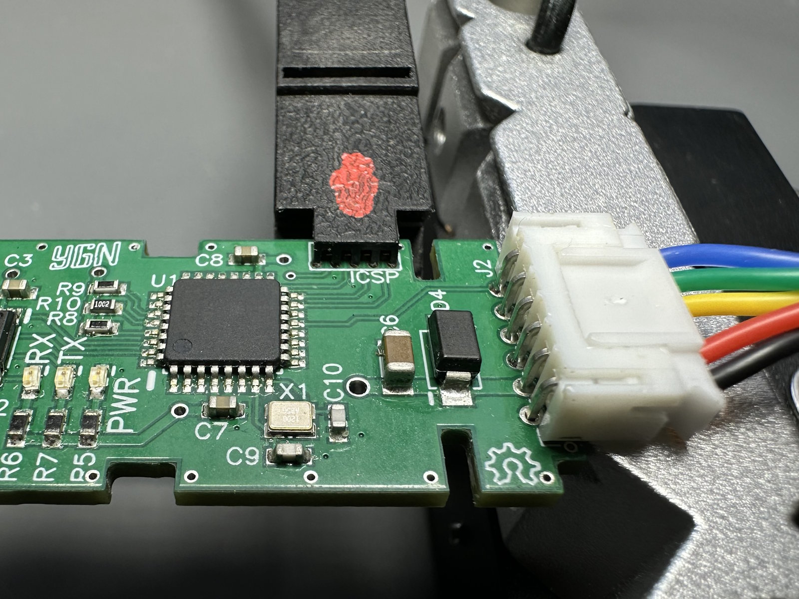
- Locate pin 1 on the programmer PCB using the photo below. It is the leftmost pin on the component side in the illustrated orientation.
- Identify pin 1 on the clip. Most clip cables mark it with a coloured wire, usually red.
- Position the pin 1 side of the clip on the component side of the PCB and align clip pin 1 with footprint pin 1.
- Press the clip into place until both jaws grip the pads evenly.
Caution: Confirm the orientation before applying power. A reversed clip can place power on the wrong pins and damage the hardware.
Tip: Mark the pin 1 side of the clip with a paint marker or a small piece of tape so you can identify it at a glance.
Make the clip-to-ISP harness
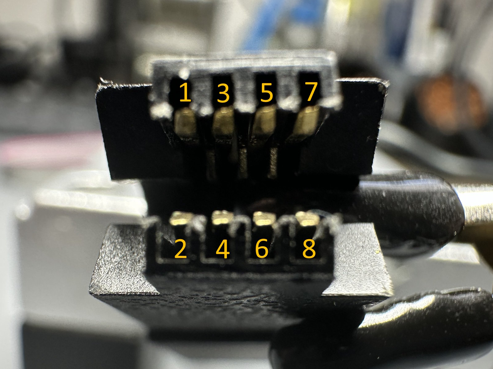
The clip’s connector has two rows of four positions, while the AVRISP MK2 uses two rows of three. The adapter harness connects the six required signals between them. Clip positions 4 and 6 remain unused.
Use the pin numbering shown in the illustrations and follow this table. The mapping is specific to the programmer board.
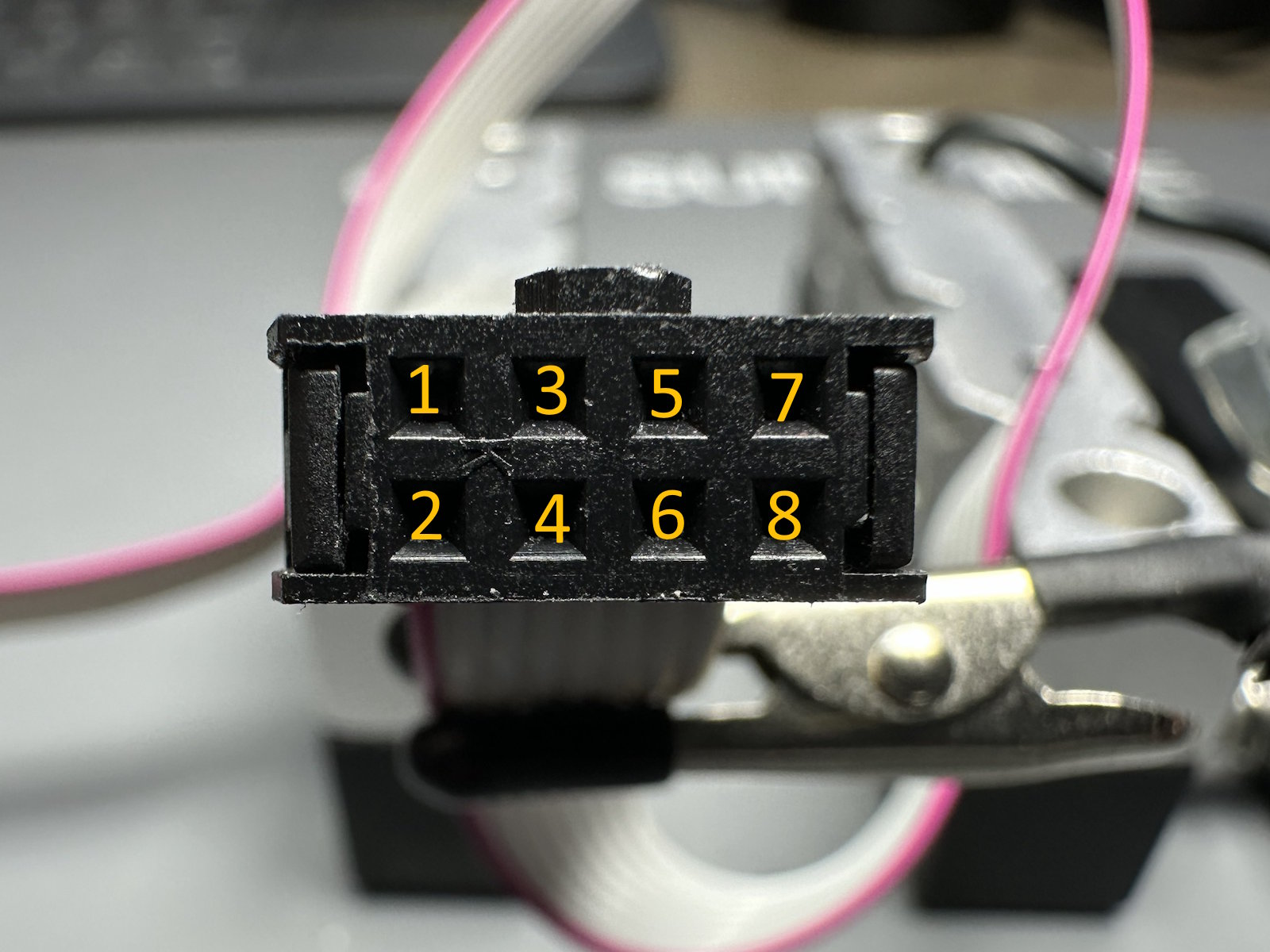
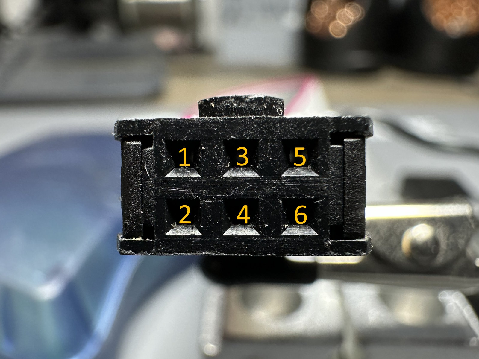
| Clip pin | Signal | AVRISP MK2 pin |
|---|---|---|
| 1 | RST | 5 |
| 2 | 3.3 V | 2 |
| 3 | SCK | 3 |
| 4 | NC | |
| 5 | MISO | 1 |
| 6 | NC | |
| 7 | MOSI | 4 |
| 8 | GND | 6 |
NC means “not connected”. Choose either harness option below.
Caution: Connector numbering appears reversed when viewed from the opposite side. Check which face each illustration shows before arranging the wires.
Option A: Individual jumper wires
Start with eight male-to-male jumper wires at the clip end. Filling all eight positions lets a zip tie hold their individual connector housings together as a stable 2×4 block. Only six wires continue to the AVRISP MK2.
- Arrange all eight jumper wires in the correct 2×4 pattern at the clip connector.
- Identify the wires in clip positions 4 and 6. These will not connect to the AVRISP MK2.
- Cut the unused AVRISP ends from those two wires, then insulate each cut end with heat-shrink tubing.
- Arrange the remaining six connector ends to match the AVRISP MK2 pinout in the table.
- Secure the eight connector housings together near the clip end with a small zip tie.
- Mark pin 1 at both ends.
Caution: Fully insulate the cut ends from positions 4 and 6. These wires only fill the unused positions in the clip-side bundle and must not contact exposed metal.
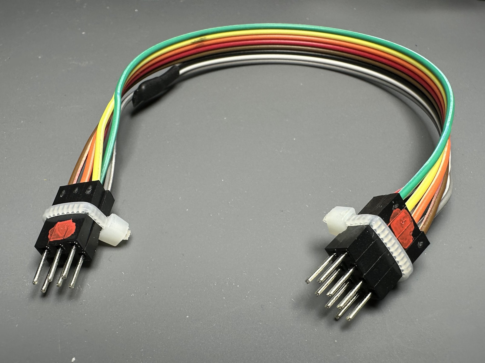
Option B: Crimped adapter harness
A crimped harness holds the terminals in connector housings, so you can reconnect the adapter without arranging individual jumper ends each time. This option needs only six wires.
- Cut six wires to the same length.
- Crimp a male terminal onto both ends of each wire.
- Insert one end into a 2×4 housing and the other into a 2×3 housing according to the wiring table.
- Leave positions 4 and 6 of the 2×4 housing empty.
- Mark pin 1 at both ends.

Check the harness
Before connecting the harness to the hardware, check that each wire reaches its intended position. This catches a swapped terminal while it is still easy to correct.
- Disconnect the harness from the clip and AVRISP MK2.
- Set your multimeter to continuity mode.
- Check each of the six connections against the wiring table. Each intended pair should show continuity.
- Check for unintended continuity between different signals, especially 3.3 V and GND.
- If a connection is wrong, correct it and repeat the checks.
- With power and USB still disconnected, connect the checked harness between the clip and AVRISP MK2.
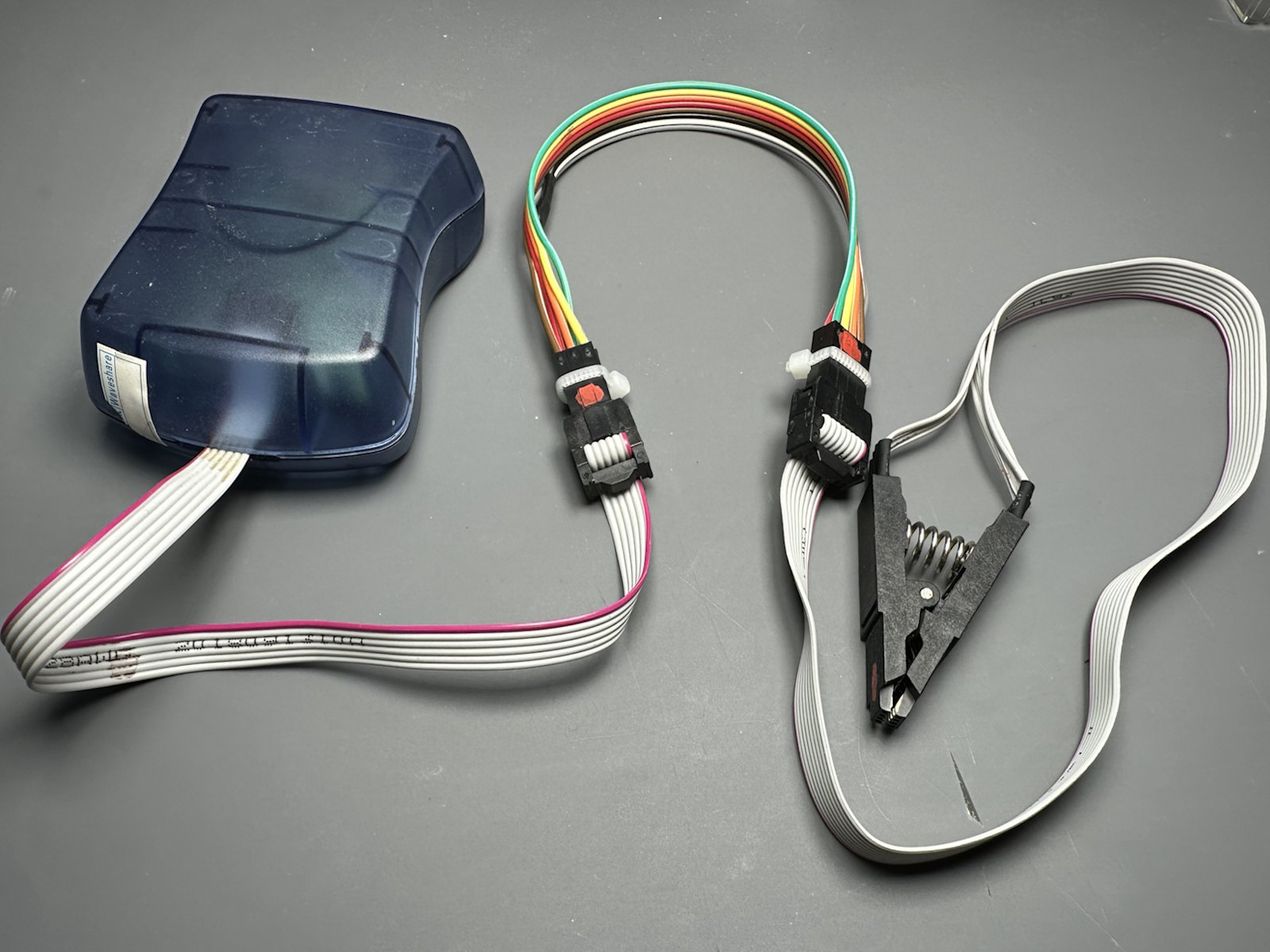
The clip and harness are now ready. Leave power disconnected while we prepare the flashing tool and firmware file.
5. Flash the Programmer Firmware
With the clip and harness ready, we can load the firmware that runs the programmer. We’ll install avrdude, download the pre-built firmware and use the AVRISP MK2 to write it into the ATmega328PB.
This loads the programmer’s own software. Your pedal’s DSP programs will go into the target EEPROM later, through SpinASM for VS Code.
Install avrdude
You don’t need an IDE or a compiler for this step. avrdude handles the connection to the AVRISP MK2 and writes the firmware file to the microcontroller.
| Platform | Installation |
|---|---|
| Linux | sudo apt install avrdude on Debian/Ubuntu, sudo dnf install avrdude on Fedora or sudo pacman -S avrdude on Arch. |
| macOS | With Homebrew installed, run brew install avrdude. |
| Windows | Download a Windows build from the official AVRDUDE releases, extract it and add the folder containing avrdude.exe to your PATH. |
Open a new terminal and run avrdude without arguments. It should display its command-line options. If the command isn’t found, check the installation and PATH before continuing.
Locate the firmware
Download vscode-spinasm-firmware.hex from the FV-1 platform repository, or locate it in your checkout under:
firmware/_output/vscode-spinasm-firmware.hex
Open a terminal in the folder containing the file. If you downloaded it separately, that can simply be your download folder.
Connect and power the programmer
The AVRISP MK2 communicates directly over USB, so you don’t need to identify a serial port. The FV-1 programmer still needs its separate 3.3 V supply.
- Switch off the target board or bench power supply and disconnect both the AVRISP MK2 and FV-1 programmer from USB.
- Attach the SOIC8 clip to the SOICBite footprint, checking pin 1 and the contact alignment.
- Connect the checked harness between the clip and AVRISP MK2 if it isn’t already attached.
- Connect your chosen power source: the target board’s programming header or a bench supply connected to the programmer’s 3.3 V and GND pins. Keep the source switched off while making these connections.
- If using a bench supply, confirm its voltage setting and polarity.
- Switch on the 3.3 V power source.
- Plug the AVRISP MK2 into your computer. Leave the FV-1 programmer’s own USB connection disconnected for this step.
Caution: Use only one power source. If you are powering the programmer from a bench supply, leave the target board disconnected.

Run the flash command
The command below writes both the firmware and the microcontroller’s fuse settings. Fuses are persistent configuration settings that control how the chip operates; they are separate from the firmware itself.
Caution: These fuse values are specific to the YGN FV-1 programmer hardware. Do not use this command for the Arduino Pro Mini or an unrelated ATmega328PB board.
Run this command as a single line from the folder containing the firmware:
avrdude -p atmega328pb -c stk500v2 -P usb -U lfuse:w:0xFF:m -U hfuse:w:0xD7:m -U efuse:w:0xF5:m -U flash:w:./vscode-spinasm-firmware.hex:i
Keep the power and clip connections steady while it runs. avrdude writes the requested settings and firmware, then reads them back to verify the result.
Confirm the result
A successful run reports that each fuse and the firmware were written and verified. The output will look similar to this:
Processing -U lfuse:w:0xFF:m
Reading 1 byte for lfuse from input file 0xFF
Writing 1 byte (0xFF) to lfuse, 1 byte written, 1 verified

Processing -U hfuse:w:0xD7:m
Reading 1 byte for hfuse from input file 0xD7
Writing 1 byte (0xD7) to hfuse, 1 byte written, 1 verified

Processing -U efuse:w:0xF5:m
Reading 1 byte for efuse from input file 0xF5
Writing 1 byte (0xF5) to efuse, 1 byte written, 1 verified

Processing -U flash:w:./vscode-spinasm-firmware.hex:i
Reading 6148 bytes for flash from input file vscode-spinasm-firmware.hex
Writing 6148 bytes to flash
Writing | ################################################## | 100% 1.88 s
Reading | ################################################## | 100% 1.81 s
6148 bytes of flash verified

Avrdude done.  Thank you.
The byte count and timings may differ between firmware builds. Look for confirmation that the flash was verified, with no errors, and let the command finish before disconnecting anything.
Tip: If flashing fails, keep the error message and start with the matching entry in Troubleshooting. A USB-access error, a missing firmware file and a communication timeout need different checks.
Once verification succeeds, unplug the AVRISP MK2, switch off the 3.3 V supply and remove the clip. The microcontroller now has its programmer firmware. Next, we’ll configure the FT230X USB bridge.
6. Configure the FT230X
The microcontroller now has its firmware. Next, we’ll configure the FT230X, the USB-to-serial bridge that connects it to your computer.
Alongside its serial connection, the FT230X has four configurable pins called CBUS pins. Their settings tell the chip which functions to assign to those connections. On this programmer, they provide transmit and receive activity signals and detect whether USB power is present.
Set them as follows:
| CBUS pin | Function | Purpose |
|---|---|---|
| CBUS0 | TXLED |
Drives the transmit activity indicator. |
| CBUS1 | TRISTATE |
Leaves the pin electrically inactive rather than driving an output. |
| CBUS2 | VBUS_SENSE |
Detects the presence of USB power, called VBUS. |
| CBUS3 | RXLED |
Drives the receive activity indicator. |
VBUS detection and board power serve different purposes here. The FT230X senses the USB connection, but the programmer still runs from its external 3.3 V supply. FT230X datasheet
Choose FT_PROG on Windows or ftdi_eeprom on Linux or macOS below. You only need to complete one route.
Connect power and USB
- Switch off the target board or bench supply and disconnect the programmer from USB.
- Remove the SOIC clip if it is still attached. The AVRISP MK2 is no longer needed.
- Connect one power source: the target board’s programming header or a bench supply connected to the programmer’s 3.3 V and GND pins.
- If using a bench supply, confirm its voltage setting and polarity. Leave the target board disconnected.
- Disconnect any other FTDI devices from your computer so you don’t accidentally configure the wrong one.
- Switch on the 3.3 V supply.
- Connect the FV-1 programmer’s own USB port to your computer.
Option A: FT_PROG on Windows
FT_PROG gives you a graphical view of the FT230X settings.
- Download and install FT_PROG from the FTDI website.
- Open FT_PROG.
- Select Devices > Scan and Parse to find the connected FT230X.
- Select the FT230X in the device tree.
- Navigate to Hardware Specific > CBUS Pins.
- Set CBUS0 through CBUS3 to the functions in the table above.
- Review all four settings, then select Devices > Program and confirm the programming operation.
- Wait for programming to finish without errors.

Once programming finishes, continue to Restart and check the configuration below.
Option B: ftdi_eeprom on Linux or macOS
ftdi_eeprom configures the chip from a text file. Install it using the command for your platform:
| Platform | Installation |
|---|---|
| Debian/Ubuntu | sudo apt install ftdi-eeprom |
| Fedora | sudo dnf install libftdi-devel |
| macOS | With Homebrew installed, run brew install libftdi. |
Fedora packages the utility with libftdi-devel. Fedora package contents
Download vscode-spinasm-ftdi.conf from the FV-1 platform repository, or create a file with that name and the following content:
vendor_id="0x0403"
product_id="0x6015"

manufacturer="YGN"
product="vscode-spinasm programmer v1.0"
serial="001"
use_serial=true

max_power=0
self_powered=true
remote_wakeup=false

cbusx0=TXLED
cbusx1=TRISTATE
cbusx2=VBUS_SENSE
cbusx3=RXLED
The file contains the four CBUS assignments along with the device’s USB identification and power settings. Keep the supplied values when following this guide.
- Open a terminal in the folder containing
vscode-spinasm-ftdi.conf. -
Run:
ftdi_eeprom --flash-eeprom vscode-spinasm-ftdi.conf - Wait for the command to finish and check that it reports no errors.
A successful run will look similar to this:
FTDI eeprom generator v0.17
(c) Intra2net AG and the libftdi developers <opensource@intra2net.com>
FTDI read eeprom: 0
EEPROM size: 256
Used eeprom space: 240 bytes
FTDI write eeprom: 0
Writing to file: eeprom.bin
FTDI close: 0
Tip: If the tool cannot access the FT230X, keep the exact error message for Troubleshooting. This operation accesses the USB device directly; it does not use a serial-port name such as
/dev/ttyUSB0.
Restart and check the configuration
After either tool finishes, restart the programmer so the FT230X loads its new settings. Removing USB alone is not enough because the board has a separate power supply.
- Disconnect the programmer from USB.
- Switch off its 3.3 V power source.
- Switch on the 3.3 V supply again.
- Reconnect USB.
If you used FT_PROG, run Devices > Scan and Parse again and check that the four CBUS assignments match the table.
Both one-time setup tasks are now complete. Next, we’ll connect the programmer for normal use and confirm communication with the target EEPROM through SpinASM.
7. Connect and Test the Programmer
With the firmware flashed and the FT230X configured, we’re ready to connect the programmer for normal use. The target board will supply power to the programmer and EEPROM, while USB carries communication with your computer.
We’ll finish with an upload and read-back check through SpinASM. This tests the complete path from your compiled program to the target EEPROM.
Connect to the target board
- Disconnect the programmer from USB and switch off the target board. If a bench supply is still attached, switch it off too.
- Disconnect the bench supply from the programmer. It is no longer needed.
- Remove the SOIC clip if it is still attached.
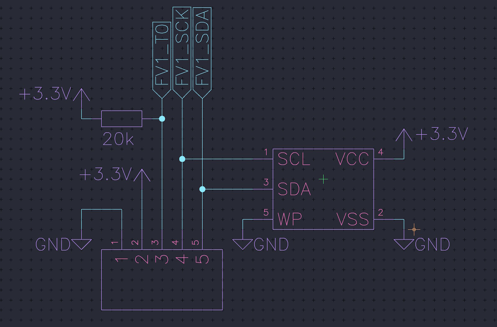
- Connect the programmer to the target board’s dedicated programming header. Match SDA, SCL, FV-1 RESET, 3.3 V and GND as shown below.
- Check each connection against the pinout before applying power.
The FV-1 RESET connection belongs to the target board. It is separate from the ATmega328PB reset connection we used through the SOIC clip during firmware flashing.
Caution: Leave the bench supply disconnected during normal EEPROM programming. The target board supplies the programmer’s 3.3 V power.

Power up the complete setup
- Power on the target board. It now supplies the programmer and target EEPROM.
- Connect the programmer’s USB port to your computer.
USB alone does not power this programmer. If the target board is switched off, connecting the USB cable will not make the complete setup ready.
Continue in SpinASM for VS Code
Follow the Program an EEPROM section of the SpinASM for VS Code guide. Both this dedicated programmer and the Arduino Pro Mini setup use that same workflow.
Start with auto-detection and the hardware-connection check, then compile and upload a program. Each stage confirms a little more of the setup:
- Auto-detection finds a serial port where compatible programmer firmware responds.
- Check Hardware Connection checks the configured compiler, programmer response and target EEPROM readiness.
- Upload and read-back verification confirms that the data read from the EEPROM matches the compiled program.
Once the upload passes verification, your programmer is ready to use. Keep this target-board connection for future EEPROM uploads; the AVRISP MK2 and SOIC clip are only needed when flashing the programmer’s own firmware again.
Tip: If a check fails, use the matching entry in Troubleshooting below. Disconnect USB and switch off the target board before adjusting any connections.
8. Troubleshooting
If something doesn’t work, start with the message reported by avrdude, the FT230X configuration tool or SpinASM. It helps identify which part of the setup needs attention: the USB connection, programmer firmware or target EEPROM.
Caution: Disconnect USB and switch off the power source before changing any wiring or repositioning the SOIC clip. During setup, use either target-board power or a bench supply. During normal EEPROM programming, use target-board power only.
avrdude cannot find the AVRISP MK2
A message such as usbdev_open(): did not find any USB device "usb" means avrdude cannot access the AVRISP MK2.
Check that the AVRISP MK2 itself is connected to your computer. Connecting only the FV-1 programmer’s USB port does not provide the connection used for firmware flashing.
On Linux, a permission error may require a udev rule or membership in an appropriate device-access group. Follow your distribution’s instructions for USB-device access. On Windows, confirm that the installed USB driver is compatible with your avrdude package.
avrdude cannot find the firmware file
Check that your terminal is open in the folder containing vscode-spinasm-firmware.hex and that the filename matches the command exactly.
The ./ in ./vscode-spinasm-firmware.hex means “in the current folder”. If you downloaded the file separately, you can run the command from that download folder.
avrdude times out or reports initialization failed
The AVRISP MK2 is not getting the expected response from the ATmega328PB. Start with power and the temporary clip connection.
- Disconnect the AVRISP MK2 from USB and switch off the programmer’s power source.
- Check the 3.3 V and GND connections. The AVRISP MK2 does not supply power to the board.
- Check pin 1 and reseat the SOIC clip so every contact sits over its pad.
- Check the adapter harness against the wiring table in Prepare the SOIC Clip.
- Switch on the 3.3 V supply, reconnect the AVRISP MK2 to USB and retry the flash command.
A loose clip contact can interrupt communication even when the harness is wired correctly. Check its seating before changing command settings.
The FT230X configuration tool cannot find or open the device
Check that the programmer has its external 3.3 V supply and that its own USB port is connected to your computer. The AVRISP MK2 is not used for this stage.
Close SpinASM connections, serial monitors and other applications that may be using the programmer, then retry the configuration tool.
On Linux, ftdi_eeprom needs access to the USB device itself. Serial-port permissions alone may not resolve an access error. Follow your distribution’s instructions for FTDI USB-device access.
Caution: Keep other FTDI devices disconnected while writing the configuration so you don’t program the wrong device.
The FT230X settings do not appear to have taken effect
First, confirm that the configuration tool finished without errors. Then disconnect USB, switch off the external 3.3 V supply, switch it on again and reconnect USB.
Removing USB alone leaves the externally powered chip running. Both connections must be cycled as described in Configure the FT230X.
If you used FT_PROG, scan the device again and compare all four CBUS assignments with the guide’s table.
SpinASM cannot detect the programmer
Confirm that the target board is powered. It supplies the programmer during normal use; USB alone does not power it.
With USB disconnected and the target board switched off, check the 3.3 V and GND connections between the two boards. Confirm that firmware flashing and FT230X configuration both completed successfully.
Power on the target board, reconnect USB and retry auto-detection. You can also run SpinASM: Select Serial Port… to choose the programmer manually, then run SpinASM: Check Hardware Connection.
Selecting a port manually does not itself confirm that the programmer responds.
Hardware check cannot reach the EEPROM
If SpinASM reports that the EEPROM is not ready, check the target board’s power and programming-header connections.
- Disconnect USB and switch off the target board.
- Check SDA, SCL, FV-1 RESET, 3.3 V and GND against the connection illustration.
- Check for loose contacts and keep the connecting wires short.
- Power on the target board, reconnect USB and run SpinASM: Check Hardware Connection again.
Note: The hardware check also checks the compiler. If the error names the compiler rather than the programmer or EEPROM, follow the SpinASM for VS Code guide to check the software setup.
Upload read-back verification fails
A verification mismatch means the data read from the EEPROM does not match the compiled program. Don’t treat that upload as successful.
- Disconnect USB and switch off the target board.
- Check the SDA, SCL, FV-1 RESET and ground connections for loose contacts.
- Confirm that the programmer is supplied by the target board and the bench supply is disconnected.
- Power on the target board and reconnect USB.
- Run SpinASM: Check Hardware Connection, then retry the upload if the check passes.
If verification still fails, keep the exact error and the SpinASM output log so there’s a clear record of where the operation stopped.
Found an Issue?
Help improve this documentation by reporting errors or suggesting improvements.